


59
Chapter 5 - Installation
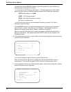
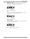
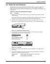
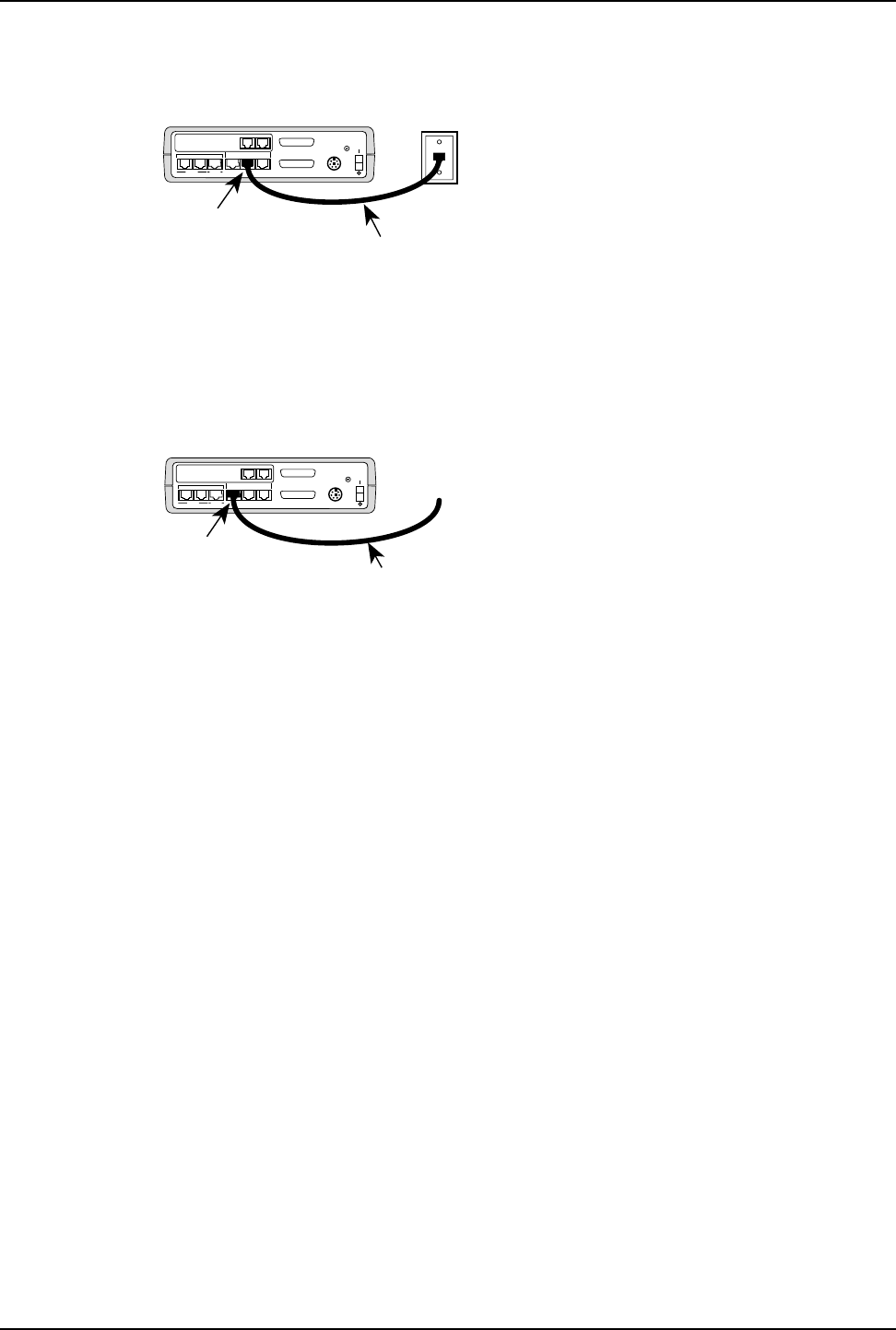
If you are connecting the voice/fax channel to the station side of a PBX, connect an RJ-11
phone cable from the VOICE/FAX CHANNEL FXO connector on the DataTalker to the station
side of the PBX. Refer to the PBX manual for the station side connection.
MODEM
DSU/TA
DIAL-UP LEASED DIGITAL
VOICE/FAX CHANNEL 1
FXO FXS
EXTERNAL COMPOSITE
DATA/COMMAND
RS232C/V.35
E&M
INTERNAL COMPOSITE
POWER
GND
VOICE/FAX CHANNEL 2
RJ-11 Phone Cable
VOICE/FAX
CHANNEL 1
FXO Connector
Figure 5-9. PBX Connection
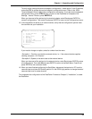
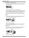
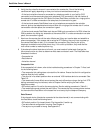
If you are connecting the voice/fax channel to a PBX E&M trunk, connect an RJ-48 phone
cable from the VOICE/FAX CHANNEL 1 E&M connector on the DataTalker to an E&M trunk
connector on the PBX. (Voice/Fax Channel 2 does not have an E&M connector.) Also, run a
ground wire from the ground connector on the back of the DataTalker or RackTalker to frame
ground on the PBX E&M trunk. Refer to the PBX manual for the trunk connection.
MODEM
DSU/TA
DIAL-UP LEASED DIGITAL
VOICE/FAX CHANNEL 1
FXO FXS
EXTERNAL COMPOSITE
DATA/COMMAND
RS232C/V.35
E&M
INTERNAL COMPOSITE
POWER
GND
VOICE/FAX CHANNEL 2
RJ-48 Cable
VOICE/FAX
CHANNEL 1
E&M Connector
To PBX
Trunk
Figure 5-10. PBX E&M Trunk Connection
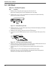
This completes the cabling of your DataTalker. Proceed to Table 5-3 to power on and test your
unit.