


25
Chapter 2 - Configuration
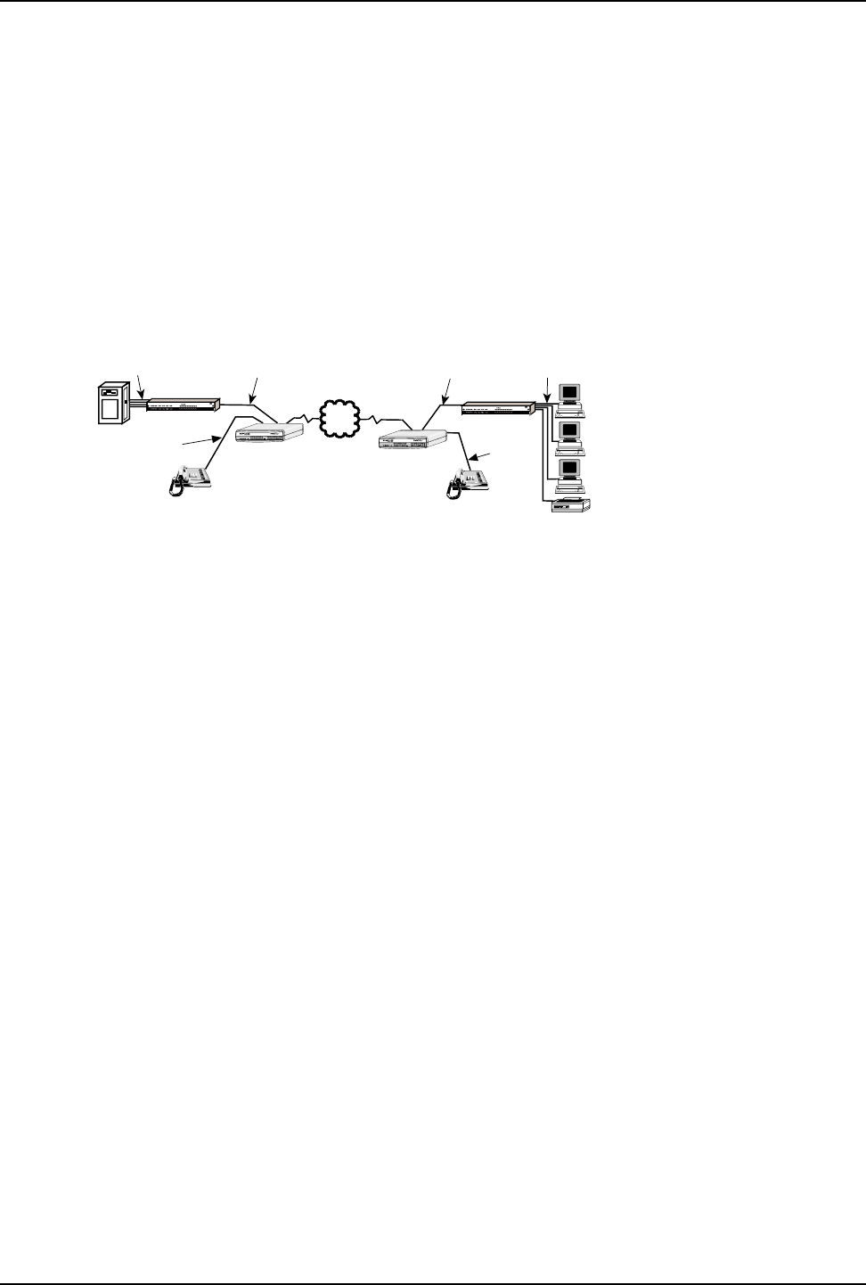
2.3 Configuration 2 - MMH900 Series with Voice/Fax
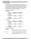
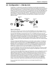
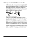
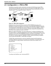
Configuration 2 adds voice capability to an existing data-only network using the same composite
link. The example shown in Figure 2-2 had an existing data-only network consisting of a MultiMux
MMH904C multiplexer connected to a host computer at the local site and a second MMH904C
connected to terminals and/or PCs and a shared printer at the remote site. To add voice
capability, a DataTalker is added between the composite link of the MMH904 and the public data
network (PDN) at both sites. The composite link between the two sites is now moved from the
MMH904 multiplexer to the new DataTalker. The composite link of the MultiMux MMH904 is
reconfigured as an external synchronous link device and connected to the synchronous data
channel of the DataTalker. The voice capability is added by connecting a telephone to the FXS
port on the back panel of the DataTalker at each site and configuring the voice/fax channel of the
DataTalkers for FXS to FXS. Now, while you are transferring data over the composite link, you
can pick up the telephone and have a simultaneous voice conversation.
Printer
Asynchronous
Channel
Voice/Fax
Channel
Local Site
Composite Link
Asynchronous
Channel
Remote Site
Voice/Fax
Channel
Telephone
PDN
DTR
OH
Statistical Multiplexer
R
E
T
R
A
N
S
M
IT
1
2
3
BUFFER
FULLNESS
LEVEL
F
L
O
C
T
R
L
R
C
V
L
I
N
K
A
L
A
R
M
R
E
M
O
T
E
D
W
N
T
E
S
T
M
O
D
E
MultiMux
Internal Composite Link
MMH2834 CD RCV XMT CTS 28.8 24.0 19.2 14.4 OH TR EC DBUP
DSU CD RCV XMT CTS 56 19.2 RTS NS OOS TM
V29/V33 Modem CD RCV XMT CTS
External Composite Link
Channel TwoChannel ThreeChannel Four
Command Modem
Channel Five
Channel SixChannel Seven
Channel Eight
XMTRCV XMTRCV XMTRCV
A
S
Y
N
C
L
I
N
K
5
6
K
D
S
U
V
2
9
/
V
3
3
RCV
Channel one
RCV
XMT
CD
RCV
XMT
CTS
V.35
XMTRCV
XMT
RCV XMTXMTRCV
XMT
RCV
INTERNAL LINK DEVICE
(Modems)
Systems
MultiTech
M
M
H
2
8
3
4
CD
MultiMux MMH904
Telephone
Sync Data
Channel
DTR
OH
Statistical Multiplexer
R
E
T
R
A
N
S
M
IT
1
2
3
BUFFER
FULLNESS
LEVEL
F
L
O
C
T
R
L
R
C
V
L
I
N
K
A
L
A
R
M
R
E
M
O
T
E
D
W
N
T
E
S
T
M
O
D
E
MultiMux
Internal Composite Link
MMH2834 CD RCV XMT CTS 28.8 24.0 19.2 14.4 OH TR EC DBUP
DSU CD RCV XMT CTS 56 19.2 RTS NS OOS TM
V29/V33 Modem CD RCV XMT CTS
External Composite Link
Channel Two
Channel Three
Channel Four
Command Modem
Channel Five
Channel SixChannel Seven
Channel Eight
XMTRCV XMTRCV XMTRCV
A
S
Y
N
C
L
I
N
K
5
6
K
D
S
U
V
2
9
/
V
3
3
RCV
Channel one
RCV
XMT
CD
RCV
XMT
CTS
V.35
XMTRCV
XMT
RCV XMTXMTRCV
XMT
RCV
INTERNAL LINK DEVICE
(Modems)
Systems
MultiTech
M
M
H
2
8
3
4
CD
MultiMux MMH904
Sync Data
Channel
DataTalker
DataTalker
COMPOSITE
LINK
STATUS
VOICE /
FAX 1
DATA/
COMMAND
ORIG
101 MDM/TA
RXTFCR RDTMV35EXTMDMDSU
CDRCV XMTCTS56RTS NSOOS
28.8 OHDBUP
TA
DTR
2B
FXSFXOE&MFAXXMTRCVXSGRSGCOMXMT RCVFC
VOICE /
FAX 2
RSGXSGRCVXMTFAXE&MFXOFXS
Data / Voice / Fax Concentrator
COMPOSITE
LINK
STATUS
VOICE /
FAX 1
DATA/
COMMAND
ORIG
101 MDM/TA
RXTFCR RDTMV35EXTMDMDSU
CDRCV XMTCTS56RTS NSOOS
28.8 OHDBUP
TA
DTR
2B
FXSFXOE&MFAXXMTRCVXSGRSGCOMXMT RCVFC
VOICE /
FAX 2
RSGXSGRCVXMTFAXE&MFXOFXS
Data / Voice / Fax Concentrator
Figure 2-2. Adding Voice to Data-Only Network
The async channels of the MultiMux MMH904s operate the same way as in the data-only
network. The MMH904 is reconfigured for an external link device by changing the 8-position DIP
switch position 2 to the down (closed) position, ensuring that the composite link is configured for
sync mode, and setting clocking to External. An RS232C cable can now be connected to the
COMPOSITE LINK EXTERNAL RS232C/V.35 connector on the back panel of the MMH904.
The composite link connection of the DataTalker to the PDN depends on the type of link device
being used. If the link device is an internal 33.6K bps modem, connect the Modem DIAL-UP or
LEASED connector to the PDN. If the link device is an internal DSU or ISDN terminal adapter,
connect the DSU/TA DIGITAL connector to the PDN. If an external link device is used, cable it to
the EXTERNAL COMPOSITE RS232C/V.35 connector. The connection type depends on whether
the interface of the external link device is RS232C or V.35. If it is V.35, a shunt on the main board
of the DataTalker must be moved to the V.35 position.
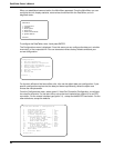
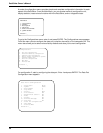
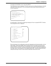
You must configure the DataTalker before you connect it to the MultiMux MMH904. To configure
the DataTalker, place DIP switch position 3 in the down (closed) position and connect a command
port device such as a terminal or a PC to the DATA/COMMAND connector on the back of the
DataTalker. Turn on the DataTalker and PC and run your communications software in terminal
mode. (Set it for direct connection at a serial port speed of 19,200 bps or slower.) Press the
ENTER key to establish communications with DataTalker
and see the Main Menu.