


42
DataTalker Owner’s Manual
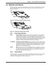
3.4.3 DIP Switch
The eight-position DIP switch is accessible through a cutout in the left side of the DataTalker
series enclosure; its location is shown in Figures 3-3 and 3-4.
Position 1: Not used
Position 2: OPEN (up) Internal composite link device selected
Closed (down) External composite link device selected
Position 3: OPEN (up) Data channel selected
Closed (down) Command channel selected
Position 4: Not used
Position 5: OPEN (up) MMV8/16/32 mode—for communicating with an
MMV800-, MMV1600-, or MMV3200-series mux
Closed (down) 101 mode—for communicating with an MMV101
or a DataTalker
Position 6: Not used
Position 7: Not used
Position 8: Not used
3.4.4 RS232C/V.35 Shunt
You can connect an external composite link device using either an RS232/V.24 or a V.35
interface to the DataTalker’s External Composite connector. To configure the DataTalker for V.35
operation you must move a shunt on the main circuit board. Two shunt sockets are located on
the back left side of the board (Figures 3-3 and 3-4). When an external composite link device with
an RS232C/V.24 interface is connected to the composite link, the shunt is installed in the RS232
socket (factory default). When the external composite link device has a V.35 interface, you must
move the shunt from the default RS232 socket to the V.35 socket. The V.35 indicator on the front
panel lights when the shunt is in the V.35 position.