


36
DataTalker Owner’s Manual
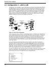
3.1 Introduction
This chapter describes the DataTalker front and back panels and switches. The front panel
contains LED indicators for the data channel device, voice/fax channels, and the composite link.
It also contains one or two switches, depending on whether it is a desktop or rack version. The
back panel contains connectors for the data/command device, internal and external composite
link devices, and the voice/fax channel devices. The desktop version also has a power switch.
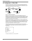
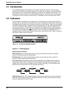
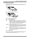
3.2 Indicators
The DataTalker is equipped with a complete set of LED indicators on the front panel that show
precisely what is occurring on the network at all times. By periodically checking the indicators you
can keep abreast of system activity without tying up the channel device. There are three groups
of indicators: data/command, voice/fax channel, and composite link. Use black legends on dual
function composite link indicators with an internal DSU, blue legends with an internal modem,
and underlined legends, such as TA, with an ISDN terminal adapter. On the desktop DataTalker
the indicators are arranged horizontally, whereas on the rack-mounted DataTalker they are
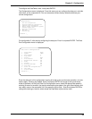
arranged vertically, but the relative position and function is the same on each. Table 3-1 explains
the function of each indicator by group.
COMPOSITE
LINK
STATUS
VOICE /
FAX 1
DATA/
COMMAND
ORIG
101 MDM/TA
RXT FCR RD TM V35 EXT MDM DSU
CD RCV XMT CTS 56 RTS NS OOS
28.8 OHDBUP
TA
DTR
2B
FXS FXO E&M FAX XMT RCV XSG RSGCOMXMT RCV FC
VOICE /
FAX 2
RSGXSGRCVXMTFAXE&MFXOFXS
Data / Voice / Fax Concentrator
Figure 3-1. Front Panel (Desktop Version)
Table 3-1. LED Indicators
Data/Command Indicators
XMT (Transmit) This indicator lights when the device connected to the data or command
channel is transmitting data to the DataTalker.
RCV (Receive) This indicator lights when the device connected to the data or command
channel is receiving data from the DataTalker.
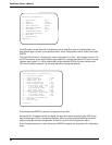
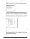
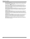
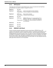
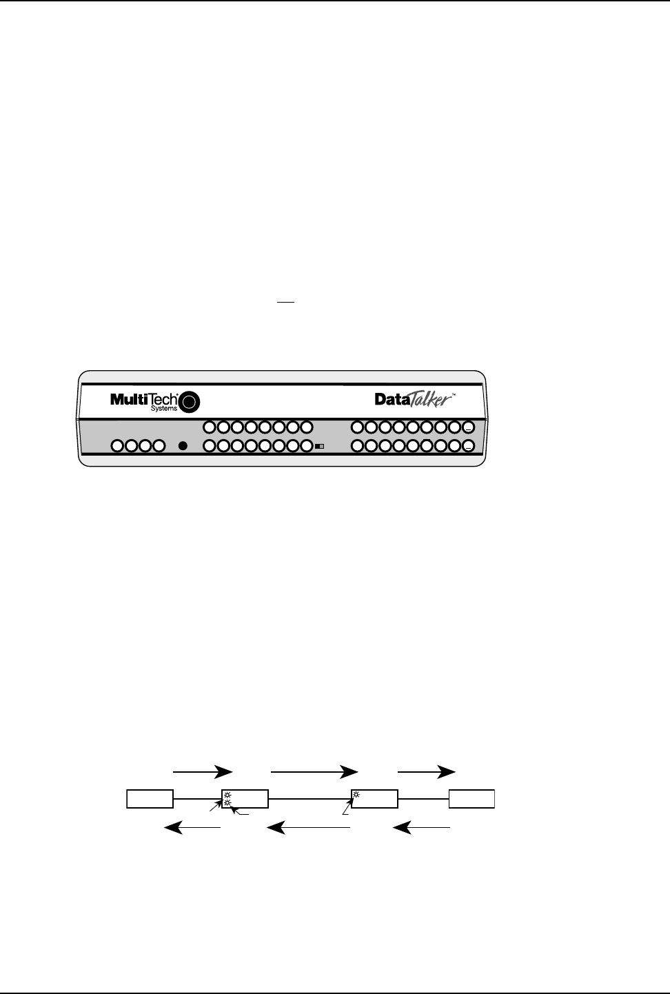
FC (Flow Control) This indicator lights when the DataTalker has stopped channel data flow
because the channel buffer is almost full. If the DataTalker stops data flow at the request of a
remote device, the Flow Control Received (FCR) indicator also lights. If the DataTalker stops
data flow for any other reason, the FCR indicator remains off.
Host
CPU
Composite
Link
Async
Channel
Async
Channel
Data Flow
FC LED ON FCR LED ON FC LED ON
Remote
Device
Flow Control
Host
DataTalker
Remote
DataTalker
COM (Command) This LED indicates whether the data or the command channel is selected. It
lights when the command channel is selected (DIP switch 3 is down), and is off when the data
channel is selected (DIP switch 3 is up).