


Contents
Chapter 1 - Introduction and Description
1.1 Introduction.................................................................................................................................... 8
1.2 About This Manual......................................................................................................................... 8
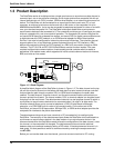
1.3 Product Description ..................................................................................................................... 10
1.4 System Features ......................................................................................................................... 12
1.4.1 Voice/Fax ........................................................................................................................... 12
1.4.2 Data Channel ..................................................................................................................... 12
1.4.3 Composite Link .................................................................................................................. 12
1.4.4 Flow Control....................................................................................................................... 12
1.4.5 Parameter Memory ............................................................................................................ 12
1.4.6 Diagnostics ........................................................................................................................ 13
1.4.7 Operational Statistics ......................................................................................................... 13
1.5 FCC Regulations for Telephone Line Interconnection ................................................................. 14
1.6 Canadian Limitations Notice ........................................................................................................ 15
1.7 Specifications .............................................................................................................................. 16
1.7.1 Async Data Channel .......................................................................................................... 16
1.7.2 Sync Data Channel ............................................................................................................ 16
1.7.3 System Control (Command Port)....................................................................................... 16
1.7.4 Composite Link .................................................................................................................. 16
1.7.5 Internal Modem .................................................................................................................. 17
1.7.6 Internal DSU ...................................................................................................................... 17
1.7.7 ISDN Terminal Adapter ......................................................................................................17
1.7.8 Voice/Fax Channel............................................................................................................. 17
1.7.9 Electrical/Physical.............................................................................................................. 18
Chapter 2 - Configuration
2.1 Introduction.................................................................................................................................. 20
2.2 Configuration 1 - Dial-Up Link ..................................................................................................... 21
2.3 Configuration 2 - MMH900 Series with Voice/Fax ....................................................................... 25
2.4 Configuration 3 - LAN to LAN ...................................................................................................... 28
2.5 Configuration 4 - PBX to PBX ..................................................................................................... 32
Chapter 3 - Front and Rear Panel Descriptions
3.1 Introduction.................................................................................................................................. 36
3.2 Indicators ..................................................................................................................................... 36
3.3 Connectors .................................................................................................................................. 39
3.3.1 Frame Ground Connector (GND) ...................................................................................... 39
3.3.2 POWER Connector ........................................................................................................... 39
3.3.3 DATA/COMMAND Connector ............................................................................................ 39
3.3.4 EXTERNAL COMPOSITE RS232C/V.35 Connector ......................................................... 39
3.3.5 VOICE/FAX CHANNEL 1 FXS Connector ......................................................................... 39
3.3.6 VOICE/FAX CHANNEL 1 FXO Connector......................................................................... 39
3.3.7 VOICE/FAX CHANNEL 1 E&M Connector ........................................................................ 40
3.3.8 DSU/TA DIGITAL Connector .............................................................................................. 40
3.3.9 MODEM LEASED Connector ............................................................................................ 40
3.3.10 MODEM DIAL-UP Connector ............................................................................................ 40
3.4 Switches and Shunts ................................................................................................................... 41
3.4.1 Front Panel Switches ......................................................................................................... 41
3.4.2 Power Switch ..................................................................................................................... 41
3.4.3 DIP Switch ......................................................................................................................... 42
3.4.4 RS232C/V.35 Shunt........................................................................................................... 42