


23
Chapter 2 - Configuration
Enter S and press ENTER to store all configurations for the main office.
Set up the home office unit the same way, except that you should switch the local and remote
interface types (FXS for the local interface and FXO for the remote interface). After you select the
home office options, enter S to store all configurations. Enter P to return to the Configurations
menu.
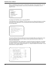
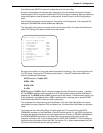
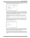
At the Configurations menu, select option 3, Composite Link Configuration. The composite link
settings for the MMH2834 internal modem are displayed.
The main office will be set up to receive a call from the home office. The home office will be set
up for DTR Dialing of the phone number at the main office.
Composite Link Settings - Internal MMH2834
1
- Enter AT commands to 2834
2 - On-Line XMT Rate: 28800
3 - Speed Setting: 33600
4
-
Dial/Leased: Dial
5 - 2 or 4 Wire: 2 Wire
6 -
Answer/Originate: Answer
7 - Transmit Level -10db
8 - DOD/DOI: On
9 - DOI Timer: 03min
10 - DOD Toggle DTR: 40sec
S - Store All Configurations
M - Main Menu
P - Previous Menu
Selection : _
Set up the main office unit to use the default composite link settings. Set up the home office unit
for DTR dialing. To set up for DTR dialing, select option 1, Enter AT Commands to 2834, and
enter the following AT commands:
ATDT[Number to Dial]N0 <CR>
AT$D1 <CR>
AT&W <CR>
Q <CR>
ATDT[Number to Dial]N0 is the AT command to store the main office phone number in location
N0. The AT$D1 command sets the modem for DTR dialing when the home office DataTalker is
powered up. The AT&W stores the $D1 command as a user default. The Q command returns you
to the Composite Link Settings menu. <CR> is shorthand for a carriage return (press ENTER).
Enter S and press ENTER to store the new configuration.
This completes the configuration of both DataTalkers. The main office DataTalker can now be
connected to the host computer, PBX, and phone line. The home office DataTalker can be taken
home.
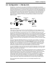
To connect the main office DataTalker, first disconnect the PC or terminal from the DATA/
COMMAND connector on the DataTalker. Place DIP switch position 3 in the OPEN (up) position
to change the data/command port over to the data channel. Connect an RS232C cable between
the DATA/COMMAND connector on the DataTalker and an asynchronous port on the host
computer. Connect an RJ-11 phone cable from the VOICE/FAX CHANNEL 1 FXO connector on
the back panel to the station side of the PBX. Connect an RJ-11 phone cable between the DIAL-
UP jack on the DataTalker and the dial-up phone line.