


©
National Instruments Corporation 2-1 PC-DIO-24/PnP User Manual
Chapter
2
Installation and
Configuration
This chapter describes how to install and configure the
PC-DIO-24/PnP.
Installation
Note:
Install your driver software before installing your hardware. Refer to your
NI-DAQ release notes for software installation instructions.
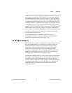
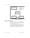
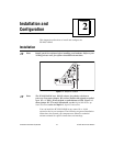
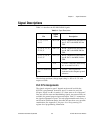
Figure 2-1.
Jumper W1 Location
Note:
The PC-DIO-24/PnP uses 100 k
Ω
resistors for polarity selection at
power-up. You can use jumper W1 to select whether data signals are pulled
up to Vcc (+5 VDC), factory default, or pulled down to GND. Figure 2-1
shows jumper W1. For more information, see the
Digital I/O Power-up
State Selection
section in Chapter 3,
Signal Connections
.
You can install the PC-DIO-24/PnP in any unused 8- or 16-bit
expansion slot in your computer. The following are general installation
instructions, but consult your computer user manual or technical
reference manual for specific instructions and warnings.
W1