


Appendix C Register-Level Programming
©
National Instruments Corporation C-3 PC-DIO-24/PnP User Manual
Register Map
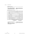
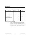
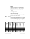
The following table lists the address map for the PC-DIO-24/PnP.
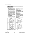
Register Description for the 82C55A
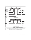
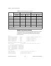
Figure C-1 shows the two control word formats used to completely
program the 82C55A. The control word flag determines which control
word format is being programmed. When the control word flag is 1,
bits 6 through 0 select the I/O characteristics of the 82C55A ports.
These bits also select the mode in which the ports are operating (that is,
mode 0, mode 1, or mode 2). When the control word flag is 0, bits 3
through 0 select the bit set/reset format of port C.
Table C-1.
PC-DIO-24/PnP Address Map
Register Name
Offset Address
(Hex)
Size Type
82C55A Register Group
PORTA Register 00 8-bit Read-and-write
PORTB Register 01 8-bit Read-and-write
PORTC Register 02 8-bit Read-and-write
CNFG Register 03 8-bit Write-only
Interrupt Control Register Group
(PC-DIO-24PnP only)
Register 1 14 8-bit Write-only
Register 2 15 8-bit Write-only