


Appendix D Using Your PC-DIO-24 (Non-PnP) Board
© National Instruments Corporation D-5 PC-DIO-24/PnP User Manual
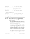
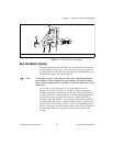
Interrupt Selection
There are two sets of jumpers for interrupt selection on the PC-DIO-24
board. W3 is used for selecting the interrupt enable line. W2 is for
selecting the interrupt level. The location of these jumpers is shown in
Figure D-1.
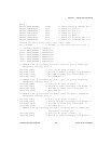
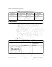
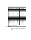
Table D-3.
Example Switch Settings with Corresponding Base I/O Address and I/O Address Space
Switch Setting
Base I/O
Address (hex)
I/O Address
Space Used (hex)
A9 A8 A7 A6 A5 A4 A3 A2
0 1 0 0 0 0 0 0 100 100–103
0 1 0 0 1 0 0 0 120 120–123
0 1 0 1 0 0 0 0 140 140–143
0 1 0 1 1 0 0 0 160 160–163
0 1 1 0 0 0 0 0 180 180–183
0 1 1 0 1 0 0 0 1A0 1A0–1A3
0 1 1 1 0 0 0 0 1C0 1C0–1C3
0 1 1 1 1 0 0 0 1E0 1E0–1E3
1 0 0 0 0 0 0 0 200 200–203
1 0 0 0 1 0 0 0 220 220–223
1 0 0 1 0 0 0 0 240 240–243
1 0 0 1 1 0 0 0 260 260–263
1 0 1 0 0 0 0 0 280 280–283
1 0 1 0 1 0 0 0 2A0 2A0–2A3
1 0 1 1 0 0 0 0 2C0 2C0–2C3
1 0 1 1 1 0 0 0 2E0 2E0–2E3
1 1 0 0 0 0 0 0 300 300–303
Note:
Base I/O address values 000 through 0FF hex are reserved for system use. Base I/O address values
100 through 3FF hex are available on the I/O channel.