


Appendix C Register-Level Programming
©
National Instruments Corporation C-19 PC-DIO-24/PnP User Manual
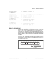
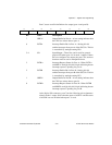
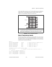
At the digital I/O connector, port C has the following pin assignments
when in mode 2. Notice that the status of STBA* and the status of
ACKA* are not included in the port C status word.
Figure C-5. Port C Pin Assignments, Mode 2
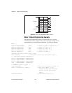
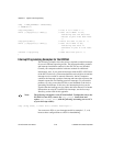
Mode 2 Programming Example
The following example shows how to configure PPI A for mode 2 input
and output and how to use the handshaking signals to control data flow.
This code is strictly an example and is not intended to be used without
modification in a practical situation.
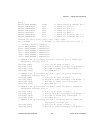
Main() {
#define BASE_ADDRESS 0x180 /* Board located at address 180 */
#define PORTAoffset 0x00 /* Offset for port A */
#define PORTBoffset 0x01 /* Offset for port B */
#define PORTCoffset 0x02 /* Offset for port C */
#define CNFGoffset 0x03 /* Offset for CNFG */
unsigned int porta, portb, portc, cnfg;
char valread; /* Variable to store data read from a port */
/* Calculate register addresses */
porta = BASE_ADDRESS + PORTAoffset;
portb = BASE_ADDRESS + PORTBoffset;
portc = BASE_ADDRESS + PORTCoffset;
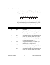
# The three port C lines associated with group B function are based on the mode selected
for group B; that is, if group B is configured for mode 0, PC2-PC0 function as general-
purpose input/output, but if group B is configured for mode 1 input or output, PC2-
PC0 function as handshaking lines as shown in the preceding mode 1 sections.
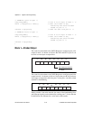
PC7
PC6
PC5
PC4
PC3
PC2
PC1
PC0
OBFA*
ACKA*
IBFA
STBA*
INTRA
#
#
#
Group A
Group B