


Chapter 2 Installation and Configuration
PC-DIO-24/PnP User Manual 2-2
©
National Instruments Corporation
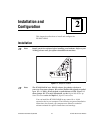
1. Turn off and unplug your computer.
2. Remove the I/O channel top cover or access port.
3. Remove the expansion slot cover on the computer back panel.
4. Insert the PC-DIO-24/PnP into any 8- or 16-bit slot. It may be a
tight fit, but
do not
force the board into place.
5. Screw the PC-DIO-24/PnP mounting bracket to the computer back
panel rail.
6. Visually verify the installation.
7. Replace the computer cover.
8. Plug in and turn on your computer.
The PC-DIO-24/PnP board is now installed.
Hardware Configuration
Plug and Play
The PC-DIO-24PnP is fully compatible with the industry-standard
Intel/Microsoft Plug and Play Specification. A Plug and Play system
arbitrates and assigns resources through software, freeing you from
manually setting switches and jumpers. These resources include the
PC-DIO-24PnP base I/O address and interrupt channel.
The Configuration Manager receives all of the resource requests at
startup, compares the available resources to those requested, and
assigns the available resources as efficiently as possible to the Plug and
Play boards. Application software can query the Configuration
Manager to determine the resources assigned to each board without
your involvement. The Plug and Play software is installed as a device
driver or as an integral component of the computer BIOS.