


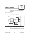

Chapter 4 Theory of Operation
PC-DIO-24/PnP User Manual 4-2
©
National Instruments Corporation
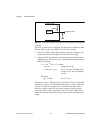
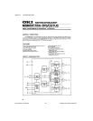
Bus Transceivers
The bus transceivers send and receive data lines and other signals to and
from the PC I/O channel.
Bus Interface
The PC-DIO-24PnP Plug and Play circuitry automatically arbitrates
and assigns system resources. Software performs all bus-related
configuration, such as setting the board base address and interrupt level.
On the PC-DIO-24 (non-PnP), switches and jumpers set the board base
address and interrupt level.
Interrupt Control Circuitry
The PC-DIO-24PnP interrupt channel is selected by the Plug and Play
circuitry. Two software-controlled registers determine what sources, if
any, can generate interrupts. The 82C55A device has two interrupt
lines, PC3 and PC0, connected to the interrupt circuitry.
The PC-DIO-24 (non-PnP) uses one of the extra PC lines
(jumper-selectable) as an interrupt enable.
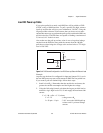
82C55A Programmable Peripheral Interface
The 82C55A PPI chip is the heart of the PC-DIO-24/PnP. This chip has
24 programmable I/O pins that represent three 8-bit ports—PA, PB, and
PC. You can program each port as an input or an output port. The
82C55A has three modes of operation—simple I/O (mode 0),
strobed I/O (mode 1), and bidirectional I/O (mode 2). In mode 1, the
three ports are divided into two groups—group A and group B. Each
group has eight data bits and three control and status bits from port C
(PC). Group A can also use mode 2. In mode 2, group A has one 8-bit
bidirectional data port and five control and status bits from port C. You
can use port A and port B in two different modes. Modes 1 and 2 use
handshaking signals from port C to synchronize data transfers. Refer to
Chapter 4,
Theory of Operation
, or to Appendix B,
OKI 82C55A Data
Sheet,
for more detailed information.