


Appendix D Using Your PC-DIO-24 (Non-PnP) Board
PC-DIO-24/PnP User Manual D-2 © National Instruments Corporation
Configuration
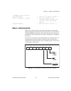
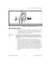
The PC-DIO-24 contains one DIP switch and two jumpers to configure
the base I/O address, interrupt level, and interrupt enable signal.
Figure D-1 shows the location of DIP switch U9 and jumper
sets W2 and W3.
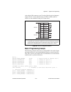
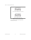
The PC-DIO-24 is configured at the factory to a base I/O address of hex
210, to use interrupt enable line PC4, and to use interrupt level 5. These
settings (shown in Table D-2) are suitable for most systems. However,
if your system has other hardware at this base I/O address, interrupt
enable line, or interrupt level, you need to change these settings on the
PC-DIO-24 (as described in the following pages) or on the other
hardware. Record your settings in the PC-DIO-24/PnP Hardware and
Software Configuration Form in Appendix E, Customer
Communication.
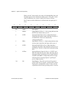
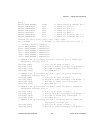
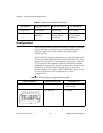
5 V supply fuse Nonresettable Self-resetting Self-resetting
Power-up state No pullups or
pulldowns
Jumper for pullup
(factory default)
or pulldown
Jumper for pullup
(factory default)
or pulldown
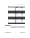
Table D-2.
PC-DIO-24 Factory-Set Jumper and Switch Settings
Base I/O Address Interrupt Enable Line Interrupt Level
Hex 210 (factory setting) PC4 (factory setting) Interrupt level 5 selected
(factory setting)
W2: Row PC4 W3: IRQ5
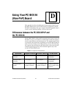
Table D-1.
Comparison of Characteristics (Continued)
Specification Original PC-DIO-24 Revised PC-DIO-24 PC-DIO-24PnP
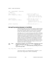
U9
A9
A8
A7
A6
A5
A4
A3
A2
87654321