


Chapter 3 Signal Connections
PC-DIO-24/PnP User Manual 3-4
©
National Instruments Corporation
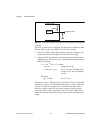
Caution: During programming, note that each time you configure any port, output
ports A and C are reset to 0, and output port B is undefined.
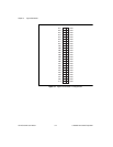
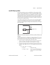
Digital I/O Signal Connections
The following specifications and ratings apply to the digital I/O lines.
The maximum input logic high and output logic high voltages assume a
Vcc supply voltage of 5.0 V.
The absolute maximum voltage rating is –0.5 to +5.5 V with respect to
GND.
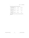
Digital input specifications (referenced to GND):
Input logic high voltage 2.2 V min 5.3 V max
Input logic low voltage –0.3 V min 0.8 V max
Input high current
(V
in
= 5 V, W1 set to pullup) — 11.0 µA max
Input high current
(V
in
= 5 V, W1 set to pulldown) — 65 µA max
Input logic low current
(V
in
= 0 V, W1 set to pullup) — –65 µA max
Input logic low current
(V
in
= 0 V, W1 set to pulldown) — –11 µA max
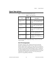
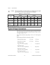
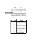
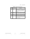
Table 3-2.
Port C Signal Assignments
Programming
Mode
Group A Group B
PC7 PC6 PC5 PC4 PC3 PC2 PC1 PC0
Mode 0 I/O I/O I/O I/O I/O I/O I/O I/O
Mode 1 Input I/O I/O IBF
A
STB
A
* INTR
A
STB
B
* IBFB
B
INTR
B
Mode 1 Output OBF
A
* ACK
A
* I/O I/O INTR
A
ACK
B
* OBF
B
* INTR
B
Mode 2 OBF
A
* ACK
A
* IBF
A
STB
A
* INTR
A
I/O I/O I/O
* Indicates that the signal is active low.
!