


Chapter 3 Signal Connections
©
National Instruments Corporation 3-7 PC-DIO-24/PnP User Manual
Power Connections
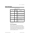
Pin 49 of the I/O connector is connected to the +5 V supply from the PC
power supply. This pin is referenced to GND and can be used to power
external digital circuitry. This +5 V supply has a 1 A self-resetting
protection fuse in series. Simply remove the circuit causing the heavy
current load and the fuse will reset itself.
Power rating 1 A at +4.65 to 5.25 V
Caution: Under no circumstances should this +5 V power pin be connected directly
to ground or to any other voltage source on the PC-DIO-24/PnP or any
other device. Doing so may damage the PC-DIO-24/PnP and the PC.
National Instruments is
NOT
liable for damage resulting from such a
connection.
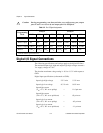
Digital I/O Power-up State Selection
You can power up the PC-DIO-24/PnP digital I/O lines in a
user-defined state. The PC-DIO-24/PnP facilitates user-configurable
pull-up or pull-down. Each DIO channel is connected to a 100 kΩ
resistor and can be pulled high or low using jumper W1. You can
use W1 to pull all 24 DIO lines high or low. However, you may want to
pull individual lines in different directions. To do this properly, you
must understand the nature of the drive current on those lines and
adhere to TTL logic levels.
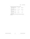
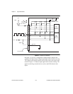
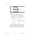
High DIO Power-up State
If you select the pulled-high mode, each DIO line will be pulled to Vcc
(approximately +5 VDC) with a 100 kΩ resistor. If you want to pull a
specific line low, connect between that line and ground a pull-down
resistor (R
L
) whose value will give you a maximum of 0.4 VDC. Using
the largest possible resistor ensures that you do not use more current
than necessary to perform the pull-down task, and that the DIO can still
drive the line. The DIO lines provide a maximum of 2.5 mA at 3.7 V in
the high state.
Also, make sure the resistor value is not so large that leakage current
from the DIO line along with the current from the 100 kΩ pull-up
resistor drives the voltage at the resistor above a TTL low level of
0.4 VDC.
!