


©
National Instruments Corporation C-1 PC-DIO-24/PnP User Manual
Register-Level
Programming
Appendix
C
This appendix describes in detail the address and function of each of the
PC-DIO-24/PnP control and status registers. This appendix also
includes important information about register-level programming on
the PC-DIO-24/PnP along with program examples written in C and
assembly language.
Note:
If you plan to do application-level programming using software such as
LabVIEW, LabWindows/CVI, or NI-DAQ with your PC-DIO-24/PnP
board, you need not read this appendix.
Introduction
You can configure your PC-DIO-24PnP board to use base addresses in
the range of 100 to 3E0 hex. Your PC-DIO-24PnP board occupies
32 bytes of address space and must be located on a 32-byte boundary.
Therefore, valid addresses include 100, 120, 140..., 3E0 hex. The base
I/O address is software-configured and does not require you to
manually change any board settings. For more information on
configuring the PC-DIO-24PnP, see Chapter 2,
Installation and
Configuration
.
The PC-DIO-24 non-PnP board occupies four bytes of address space
and must be located on a four-byte boundary. For more information on
configuring the PC-DIO-24, see Appendix D,
Using Your PC-DIO-24
(Non-PnP) Board
.
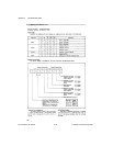
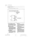
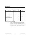
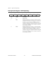
In addition to the 82C55A device, the PC-DIO-24PnP has two registers
that select which interrupt sources are capable of generating interrupts.
Individual enable bits select whether port A or port B interrupt signals
from the 82C55A device generate interrupt requests. A master interrupt
enable bit determines whether the board can actually send interrupt
requests to the host computer. The configuration bits for these registers
are defined in the
Register Description for the Interrupt Control
Registers
section in this appendix.