


Appendix C Register-Level Programming
©
National Instruments Corporation C-5 PC-DIO-24/PnP User Manual
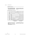
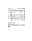
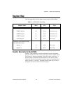
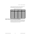
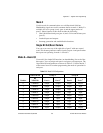
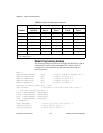
Table C-2 shows the control words for setting or resetting each bit in
port C. Notice that bit 7 of the control word is cleared when
programming the set/reset option for the bits of port C.
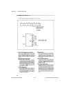
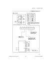
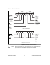
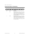
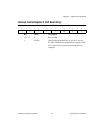
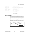
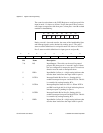
Register Description for the Interrupt Control Registers
There are two interrupt control registers on the PC-DIO-24PnP. One of
these registers has individual enable bits for the two interrupt lines from
the 82C55A device. The other register has a master interrupt enable bit.
When writing to these registers, set all reserved bits to zero. The bit
maps and signal definitions are listed as follows.
Table C-2.
Port C Set/Reset Control Words
Bit Number
Bit Set Control
Word
Bit Reset
Control Word
The Bit Set or
Reset in Port C
0 0xxx0001 0xxx0000 xxxxxxxb
1 0xxx0011 0xxx0010 xxxxxxbx
2 0xxx0101 0xxx0100 xxxxxbxx
3 0xxx0111 0xxx0110 xxxxbxxx
4 0xxx1001 0xxx1000 xxxbxxxx
5 0xxx1011 0xxx1010 xxbxxxxx
6 0xxx1101 0xxx1100 xbxxxxxx
7 0xxx1111 0xxx1110 bxxxxxxx