


Chapter 3 Signal Connections
©
National Instruments Corporation 3-3 PC-DIO-24/PnP User Manual
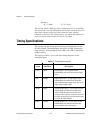
Signal Descriptions
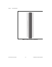
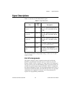
Table 3-1 describes the PC-DIO-24/PnP signals.
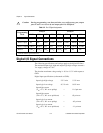
The absolute maximum voltage input rating is –0.5 to +5.5 V with
respect to GND.
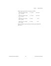
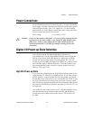
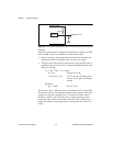
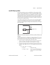
Port C Pin Assignments
The signals assigned to port C depend on the mode in which the
82C55A is programmed. In mode 0, port C is treated as one 8-bit
I/O port. If port A or B is in mode 1 or 2, then some or all of the port C
lines are used for status and handshaking signals. Any unused lines are
available for general-purpose input and output. Table 3-2 summarizes
the signal assignments of port C for each programmable mode. Ports A
and B can be in different modes; the table does not show every possible
combination. See Appendix C,
Register-Level Programming
, for
register-level programming information.
Table 3-1.
Signal Descriptions
Pin
Signal
Name
Description
1, 3, 5, 7, 9, 11,
13, 15
PC<7..0> Port C—Bidirectional data lines for
port C. PC7 is the MSB, PC0 the
LSB.
17, 19, 21, 23, 25,
27, 29, 31
PB<7..0> Port B—Bidirectional data lines for
port B. PB7 is the MSB, PB0 the
LSB.
33, 35, 37, 39, 41,
43, 45, 47
PA<7..0> Port A—Bidirectional data lines for
port B. PA7 is the MSB, PA0 the
LSB.
49 +5 V +5 Volts—This pin is fused for up
to 1 A at +4.65 to 5.25 V.
All even-numbered
pins
GND Ground—These signals are
connected to the computer ground
reference.