


Appendix D Using Your PC-DIO-24 (Non-PnP) Board
PC-DIO-24/PnP User Manual D-6 © National Instruments Corporation
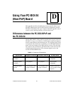
Interrupt Enable Settings
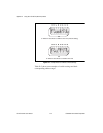
To enable interrupt requests from the PC-DIO-24, you must set
jumper W3 to select PC2, PC4, or PC6 as the active low interrupt enable
line. When the interrupt enable line is logic low, interrupts are enabled
from the PC-DIO-24 board. Refer to Chapter 4, Theory of Operation,
for the suggested interrupt enable line setting for each digital I/O mode
of operation. If W3 is set to N/C, all interrupt requests from the
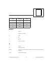
PC-DIO-24 are disabled. Figure D-3 shows the possible jumper settings
for W3. The board ships with this jumper set to PC4; therefore, interrupt
requests from the board are enabled and controlled by PC4.
Figure D-3.
Interrupt Enable Jumper Settings
Interrupt Level Settings
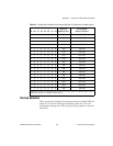
The PC-DIO-24 board can connect to any one of the six interrupt lines
of the PC I/O Channel: IRQ3, IRQ4, IRQ5, IRQ6, IRQ7, or IRQ9. You
select the interrupt line by setting a jumper on W2. To use the interrupt
capability of the board, select an interrupt line and place the jumper in
the appropriate position. The default interrupt line is IRQ5. To change
to another line, remove the jumper from IRQ5 and place it on the pins
for another request line. Figure D-4 shows the default factory setting for
IRQ5.
Figure D-4.
Interrupt Jumper Setting for IRQ5 (Factory Setting)
W3
INT
PC6
PC4
PC2
N/C
W3
INT
PC4 Selected
(Default Factory
Settin
g)
PC6 Selected Interrupt
Disabled
PC2 Selected
PC6
PC4
PC2
N/C
W3
INT
PC6
PC4
PC2
N/C
W3
INT
PC6
PC4
PC2
N/C
W2
IRQ3
IRQ4
IRQ5
IRQ6
IRQ7
IRQ9