


Chapter 3 Signal Connections
PC-DIO-24/PnP User Manual 3-6
©
National Instruments Corporation
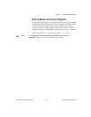
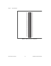
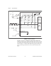
Figure 3-2. Digital I/O Connections
In Figure 3-2, port A is configured for digital output, and port B is
configured for digital input. Digital input applications include receiving
TTL signals and sensing external device states such as the state of the
switch in Figure 3-2. Digital output applications include sending TTL
signals and driving external devices such as the LED shown in this
figure.
PC-DIO-24/PnP
I/O Connector
+5 V
+5 V
LED
TTL Signal
41
43
45
47
67
71
73
69
50, 100
+5 V
Jumper
Selectable (W1)
100 kΩ 100 kΩ 100 kΩ 100 kΩ
100 kΩ100 kΩ 100 kΩ 100 kΩ
PPI
Port B
PB<7..4>
PPI
Port A
PA<3..0>
GND
Switch