


Chapter 3 Signal Connections
©
National Instruments Corporation 3-9 PC-DIO-24/PnP User Manual
Low DIO Power-up State
If you select pulled-low mode, each DIO line will be pulled to GND
(0 VDC) using a 100 kΩ resistor. To pull a specific line high, connect
a pull-up resistor that will give you a minimum of 2.8 VDC. Using the
largest possible resistance value ensures that you do not to use more
current than necessary to perform the pull-up task, and that the DIO can
still drive the line. The DIO lines are capable of sinking a maximum of
2.5 mA at 0.4 V in the low state.
Also, make sure the pull-up resistor value is not so large that leakage
current from the DIO line along with the current from the 100 kΩ
pull-down resistor brings the voltage at the resistor below a TTL high
level of 2.8 VDC.
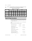
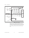
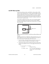
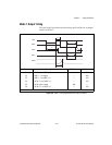
Figure 3-4.
DIO Channel Configured for Low DIO Power-up State with External Load
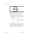
Example:
At power up, the board is configured for input and jumper W1 is set in
the low DIO power-up state, which means all DIO lines are pulled low.
If you want to pull one channel high, follow these steps:
1. Install a load (R
L
). Remember that the smaller the resistance, the
greater the current consumption and the higher the voltage.
2. Using the following formula, calculate the largest possible load to
maintain a logic high level of 2.8 V and supply the maximum sink
current.
V = I * R
L
⇒ R
L
= V / I, where:
V = 2.2 V ;voltage across R
L
I = 28 µA + 11 µA ; 2.8 V across the 100 kΩ pull-up
resistor and 11 µA max leakage
current
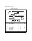
PC-DIO-24/PnP
Digital I/O Line
82C55A
+5 V
GND
100 kΩ
R
L