


©
National Instruments Corporation 3-1 PC-DIO-24/PnP User Manual
Chapter
3
Signal Connections
This chapter includes timing specifications and signal connection
instructions for the PC-DIO-24/PnP I/O connector.
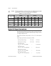
Caution:
Connections that exceed any of the maximum ratings of input or output
signals on the PC-DIO-24/PnP can damage the board and the PC. National
Instruments is
NOT
liable for any damages resulting from any such signal
connections. Maximum ratings for each signal are given in this chapter
under the discussion of that signal.
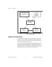
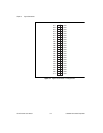
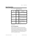
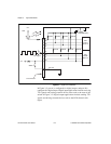
I/O Connector
Figure 3-1 shows the pin assignments for the PC-DIO-24/PnP digital
I/O connector.
!