


Appendix C Register-Level Programming
PC-DIO-24/PnP User Manual C-14
©
National Instruments Corporation
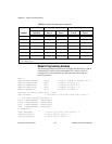
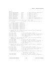
/* EXAMPLE 1–port A input */
outp(cnfg,0xB0); /* Port A is an input in mode 1. */
while (!(inp(portc) & 0x20)); /* Wait until IBFA is set,
indicating that data has been
loaded in port A. */
valread = inp(porta); /* Read the data from port A. */
/* EXAMPLE 2–Port B input */
outp(cnfg,0x86); /* Port B is an input in mode 1. */
while (!(inp(portc) & 0x02)); /* Wait until IBFB is set,
indicating that data has been
loaded in port B. */
valread = inp(portb);
}
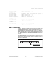
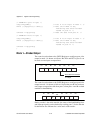
Mode 1—Strobed Output
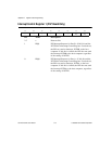
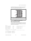
The control word written to the CNFG Register to configure port A for
output in mode 1 is shown as follows. Bits PC4 and PC5 of port C can
be used as extra input or output lines.
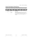
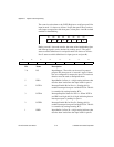
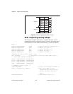
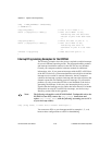
The control word written to the CNFG Register to configure port B for
output in mode 1 is shown as follows. Notice that port B does not have
extra input or output lines left from port C when ports A and B are both
enabled for handshaking.
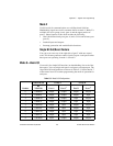
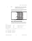
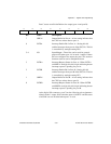
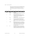
During a mode 1 data write transfer, the status of the handshaking lines
and interrupt signals can be obtained by reading port C. Notice that the
bit definitions are different for a write and a read transfer.
D2 D1 D0D3D7
D6 D5
D4
1 = input
0 = output
Port C bits PC4 and PC5
1
0
1/0
X
X
X10
D2 D1 D0D3D7
D6 D5
D4
1
X
X
X11X
X