


3-4 Administration Guide
Identify the Connectors and Attach the Cables
Identify the connectors on the back panel and attach the necessary Netopia cables.
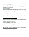
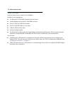
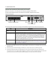
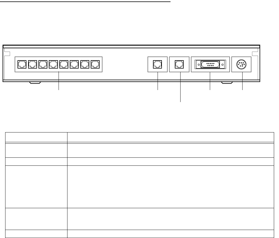
The figure below displays the back of the Netopia 4753 G.SHDSL Integrated Access Device.
Netopia 4753 back panel
The following table describes all the Netopia 4753 G.SHDSL Integrated Access Device back panel ports.
1. Connect the mini-DIN8 connector from the power adapter to the power port, and plug the other end into an
electrical outlet.
2. Connect one end of the RJ-45 cable to the DSL port, and the other end to your DSL wall outlet.
3. Connect the Ethernet cable to the Ethernet port on the unit and the other end to your Ethernet hub.
You should now have: the power adapter plugged in; the Ethernet cable connected between the router and
your Ethernet hub; and the DSL cable connected between the router and the DSL wall outlet.
Port Description
Telephone extension
ports
Eight RJ-11 telephone jacks for connecting your phone extensions.
DSL port An RJ-45 10Base-T-style jack labeled DSL for your DSL connection.
Ethernet port An RJ-45 10/100Base-T Ethernet jack. You will use this to configure the Netopia
4753. For a new installation, use the Ethernet connection. Alternatively, you can
use the console connection to run console-based management using a direct
serial connection. You can either connect your computer directly the Ethernet
port using a crossover cable, or connect both your computer and the Netopia
4753 to an existing Ethernet hub on your LAN.
Console port A DB-9 console port for a direct serial connection to the console screens. You
can use this if you are an experienced user. See “Connecting a Console Cable
to Your Device” on page 6-3.
Power port A mini-DIN8 power adapter cable connection.
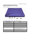
Console Power
10/100
Ethernet
DSLTelephone
Extensions
12345 786
Telephone Extension ports
DSL Line port
10/100 Ethernet port
Console port Power port