


3-4 User’s Reference Guide
II
II
dd
dd
ee
ee
nn
nn
tt
tt
ii
ii
ff
ff
yy
yy
tt
tt
hh
hh
ee
ee
cc
cc
oo
oo
nn
nn
nn
nn
ee
ee
cc
cc
tt
tt
oo
oo
rr
rr
ss
ss
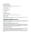
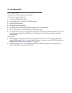
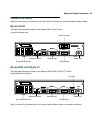
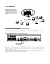
The following table describes all of the Netopia R5000 Series Router back panel ports.
AA
AA
tt
tt
tt
tt
aa
aa
cc
cc
hh
hh
tt
tt
hh
hh
ee
ee
cc
cc
aa
aa
bb
bb
ll
ll
ee
ee
ss
ss
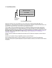
1. Connect an RJ-45 Ethernet cable to any of the Ethernet ports on the router and the Ethernet port on your
computer.
2. R5100 Serial: Connect the special DB-15 Serial cable to the Serial Line 1 port and to your external
CSU/DSU or modem.
or
R5200 DDS or R5300 T1: Connect one end of an RJ-45 Telco cable to the Line 1 port and the other end to
your T1 or DDS wall outlet.
3. Connect the mini-DIN8 connector from the power adapter to the power port, and plug the other end into an
electrical outlet.
(If you are connecting the router to an existing Ethernet hub, use Ethernet port #1 on the router and set the
crossover switch to the Uplink position.)
You should now have the power adapter plugged in, the Ethernet cable connected between the router and
your computer, and either the Serial cable connected to a CSU/DSU or modem (R5100 Serial) or the Line
cable connected between the router and the Line wall outlet (R5200 DDS and R5300 T1).
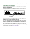
Port Description
Power port A mini-DIN8 power adapter cable connection.
Serial Line 1 port
(R5100 Serial router only)
A DB-15 serial port labelled Line 1 - Serial for your external CSU/DSU or modem
connection.
Line ports A telephone-style jack labeled “Line 1” for your T1 or DDS WAN connection. Use
the “Line 1" port, NOT “Line 2." The Line port is not used for a Serial
connection.
Console port A DB-9 console port for a direct serial connection to the management console
screens. You can use this if you are unable to connect to the console screens
using Telnet over the network. See “Connecting a console cable to your router”
on page 6-3.
Auxiliary port An HD-15 auxiliary port for attaching an external modem for remote
management or the optional AppleTalk kit.
Crossover switch A crossover switch with Normal and Uplink positions. If you use Ethernet Port
#1 for a direct Ethernet connection between a computer and the router, set the
switch to the Normal position. If you are connecting the router to an Ethernet
hub, use Ethernet port #1 on the router and set the switch to the Uplink
position.
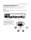
8-port Ethernet hub Eight Ethernet jacks. You will use one of these to configure the Netopia R5000
Series Router. For a new installation, use the Ethernet connection. Alternatively,
you can use the console connection to run console-based management using a
direct serial connection. You can either connect your computer directly to any of
the Ethernet ports on the router, or connect both your computer and the router
to an existing Ethernet hub on your LAN.