


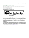

Making the Physical Connections 3-5
NN
NN
ee
ee
tt
tt
oo
oo
pp
pp
ii
ii
aa
aa
RR
RR
55
55
00
00
00
00
00
00
SS
SS
ee
ee
rr
rr
ii
ii
ee
ee
ss
ss
RR
RR
oo
oo
uu
uu
tt
tt
ee
ee
rr
rr
ss
ss
tt
tt
aa
aa
tt
tt
uu
uu
ss
ss
ll
ll
ii
ii
gg
gg
hh
hh
tt
tt
ss
ss
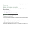
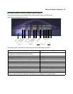
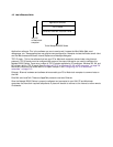
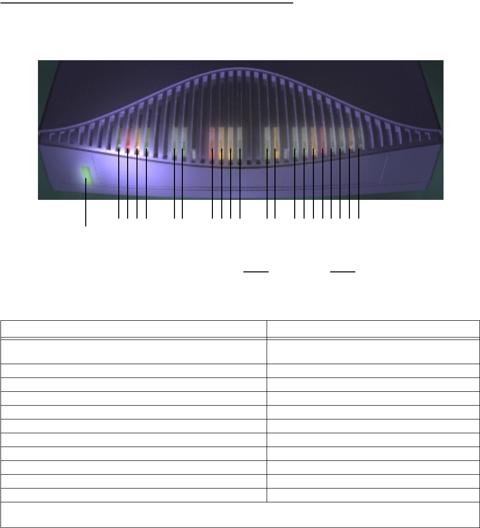
The figure below represents the Netopia R5000 Series Router status light (LED) panel.
Netopia R5000 Series Router LED front panel
The following table summarizes the meaning of the various LED states and colors:
When this happens... the LEDs...
The corresponding line passes supervisory traffic between
the WAN and the Netopia R5000 Series Router
2 flashes yellow.
The WAN interface is operational 3 is green.
The line is unavailable 3 flashes red.
The WAN has carrier 4 is green.
Data is transmitted or received on the WAN 4 flashes yellow.
Carrier is asserted 6 and 7 are green.
Data is transmitted or received 6 and 7 flash yellow.
Data is transmitted or received by the Ethernet controller 12 flashes yellow.
The Ethernet interface detects a collision 13 flashes red.
Link is detected 14 though 21 are solid green.
Data are received on their respective ports 14 though 21 flash green.
Note: Channel 2 (#5) and WAN 2 (#8 through #11) are unused, since traffic is carried only on WAN channel
1. Also, Console carrier (6) is ignored if the console is not configured for a remote modem.
2 3 4 5 6 7 8 9 10 11 12 13 14 15 16171819 20 21
Management
Ready
Channel 1
Link/Receive
Console
Auxiliary
Collision
Traffic
WAN 1 WAN 2 Ethernet
Power
1
Channel 2
Management
Ready
Channel 1
Channel 2