


Steps 387
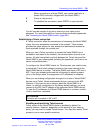
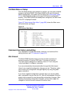
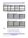
Table 60
Network devices (cont’d.)
Device/Service
VLAN ID
VLAN IP
address
Device IP address
Ethernet Routing
Switch 8600 port
Nortel SNAS
40 10.40.40.1
10.40.40.2 (RIP)
10.40.40.3 (MIP)
10.40.40.100 (pVIP)
1/7
Remediation
server
120 10.120.120.1 10.120.120.2
1/31
Call server
50 10.11.11.1 10.11.11.254
1/23
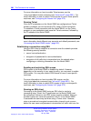
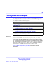
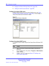
Table 61 "VLANs for the Ethernet Routing Switch 8300" (page
387) summarizes the VLANs for the Ethernet Routing Switch 8300.
Table 61
VLANs for the Ethernet Routing Switch 8300
VLAN VLAN ID Yellow subnet
Red
110
N/A
Yellow
120
10.120.120.0/24
Green
130
N/A
VoIP
140
N/A
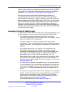
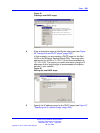
Table 62 "VLANs for the Ethernet Routing Switch 5510" (page
387) summarizes the VLANs for the Ethernet Routing Switch 5510.
Table 62
VLANs for the Ethernet Routing Switch 5510
VLAN VLAN ID Yellow subnet
Red
210
N/A
Yellow
220
10.120.120.0/24
Green
230
N/A
VoIP
240
N/A
ATTENTION
The management VLAN ID is the default (VLAN ID 1).
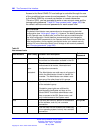
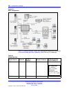
Steps
1. “Configure the network DNS server” (page 388)
2. “Configure the network DHCP server” (page 388)
3. “Configure the network core router” (page 392)
4. “Configure the Ethernet Routing Switch 8300” (page 393)
Nortel Secure Network Access Switch
Using the Command Line Interface
NN47230-100 03.01 Standard
28 July 2008
Copyright © 2007, 2008 Nortel Networks
.