


Mediant 2000 SIP
Mediant 2000 SIP User’s Manual 22 Document #: LTRT-72504
Note 1: Before removing or inserting boards from / to the chassis, attach a wrist strap
for electrostatic discharge (ESD) and connect it to the rack frame using an
alligator clip.
Note 2: Do not set components down without protecting them with a static bag.
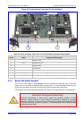
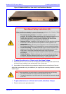
2.3.1.1 Removing Boards
To remove the TP-1610 board from the chassis, take these 3 steps:
1. Unfasten the screws on the plate of the board.
2. Press the red ejector buttons on the two black ejector/injector latches on both ends and wait
for the hot-swap blue LED to light, indicating that the board can be removed.
3. Pull on the two ejector/injector latches and ease out the board from the slot.
To remove the TP-1610 RTM from the chassis, take these 4 steps:
1. Remove the cables attached to the RTM.
2. Unfasten the screws on the brackets at both ends of the panel that secure the RTM to the
chassis.
3. Press the red ejector buttons on the two black ejector/injector latches on both ends.
4. Grasp the panel and ease the RTM board out of the slot.
2.3.1.2 Inserting Boards
To insert the TP-1610 board into the chassis, take these 6 steps:
1. Hold the board horizontally.
2. With the black ejector/injector latches in the open (pulled out) position, insert the board in the
slot, aligning the board with the grooves on each end.
3. Ease the board all the way into the slot until the ejector/injector latches touch the chassis.
The Blue hot-swap LED is lit.
4. Press the two black ejector/injector latches on both ends inward, toward the middle, until you
hear a click.
5. Wait for the hot-swap blue LED to turn off.
6. Fasten the screws on the front panel of the board to secure the board to the chassis and to
ensure that the board has a chassis earthing connection.
To insert the TP-1610 RTM into the chassis, take these 6 steps:
1. Hold the board horizontally.
2. With the black ejector/injector latches in the open (pulled out) position, insert the board in the
slot, aligning the board with the grooves on each end.
3. Ease the board all the way into the slot until the ejector/injector latches touch the chassis.
4. Press the two black ejector/injector latches on both ends inward, toward the middle until you
hear a click.
5. Fasten the screws on the front panel of the board to secure the board to the chassis and to
ensure that the board has a chassis earthing connection.
6. Reattach the cables (refer to Section
3.4 on page 30).