


Mediant 2000 SIP User’s Manual 2. Mediant 2000 Physical Description
Version 4.4 23 July 2005
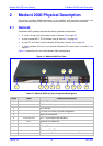
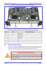
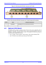
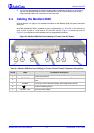
2.3.2 TP-1610 Front Panel LED Indicators
The functionality of the front panel LEDs for the TP-1610 is described in the following four tables
and illustrated in Figure
2-2 on page 21. Note that there is a choice of front panels according to
the number of channels.
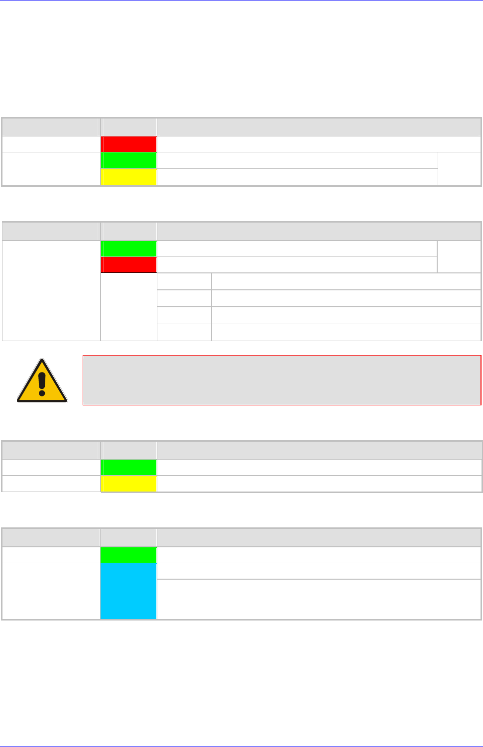
Table
2-4: Status LED Indicators
Label LED Color LED Function
FAIL Red
Normally OFF; Red indicates gateway failure (fatal error)
Green
Gateway initialization sequence terminated OK
ACT
Yellow
N/A
Bi-color
LED
Table 2-5: E1/T1 Trunk Status LED Indicators
Label LED Color Signal Description
Green
Trunk is synchronized (normal operation)
Red
Loss due to any of the following 4 signals:
Bi-color
LED
LOS
Loss of Signal
LFA
Loss of Frame Alignment
AIS
Alarm Indication Signal (the Blue Alarm)
T1/E1 Status 1 to 8
and
T1/E1 Status 9 to 16
RAI
Remote Alarm Indication (the Yellow Alarm)
Note: On the front panel 16 LEDs are provided for 16-span units and 8 LEDs are
provided for 1-span, 2-span, 4-span, and 8-span units. In the case of 1-span,
2-span and 4-span units, the extra LEDs are unused.
Table 2-6: Ethernet LED Indicators
Label LED Color LED Function
LINK Green
Link all OK
ACT Yellow
Transmit / receive activity
Table 2-7: cPCI LED Indicators
Label LED Color LED Function
PWR Green
Power is supplied to the board
The cPCI board can now be removed.
SWAP READY Blue
The cPCI board was inserted successfully.
For detailed information on the Swap-Ready LED, refer to Section
2.3.1 on page 21.
During correct Mediant 2000 operation, the ACT LED is lit green, the FAIL LED is off. Changing
of the FAIL LED to red indicates a failure.