


Mediant 2000 SIP
Mediant 2000 SIP User’s Manual 32 Document #: LTRT-72504
3. Repeat steps 1 and 2 for the other Trunk cable but this time connect it to the connector
labeled “Trunks 916”.
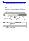
The 50-pin male Telco cable connector must be wired according to the pinout in Table
3-3 below,
and to mate with the female connector illustrated in Figure
3-5.
Figure
3-5: 50-pin Female Telco Board-Mounted Connector
125
26
50
Pin Numbers
Table 3-3: E1/T1 Connections on each 50-pin Telco Connector
E1/T1 Number
1 to 8 9 to 16
Tx Pins (Tip/Ring) Rx Pins (Tip/Ring)
1 9 27/2 26/1
2 10 29/4 28/3
3 11 31/6 30/5
4 12 33/8 32/7
5 13 35/10 34/9
6 14 37/12 36/11
7 15 39/14 38/13
8 16 41/16 40/15
With RJ-48c Connectors, take these 2 steps:
1. Connect the E1/T1 trunk cables to the ports labeled “Trunks 1 to 8” (in the case of the 8-
trunk device) on the Mediant 2000 RTM.
2. Connect the other ends of the Trunk cables to the PBX/PSTN switch.
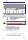
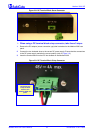
RJ-48c trunk connectors are wired according to Figure
3-6 below.
Figure
3-6: Pinout of RJ-48c Trunk Connectors
1 2 3 4 5 6 7 8
3, 6, 7, 8
not connected
body = shield
1 = Rx Ring
2 = Rx Tip
4 = Tx Ring
5 = Tx Tip
RJ-48c Connector and Pinout
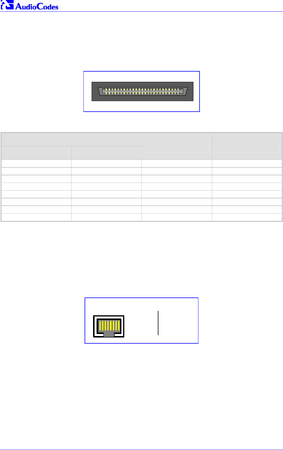
3.4.2 Installing the Ethernet Connection
Connect a standard Category 5 network cable to the Ethernet RJ-45 port (and the other as
optional redundancy/backup). Connect the other end of the Category 5 network cables to your IP
network. The Ethernet connectors (labeled Ethernet 1 and Ethernet 2) are wired according to
Figure
3-7.
Note that for redundant operation it is recommended to connect each of the Ethernet connectors
to a different Switch.
When assigning an IP address to the Mediant 2000 using HTTP (under Step
1 in Section 4.1.1),
you may be required to disconnect this cable and re-cable it differently.