


Page 132 of 332 Chapter 9 — Installing the chassis
553-3021-209 Standard 3.00 April 2000
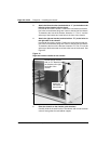
3 Attach the left ear bracket (marked with an “L”) to the holes on the
left side of the chassis (near the front).
Use two #8-32 machine screws. Position the ear bracket so that the
four holes on the bracket flange are nearer to the back of the chassis.
To determine the front of the bracket, locate the “L”. This “L” must be
at the top of the bracket and must face to the front of the chassis.
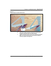
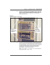
4 Attach the right ear bracket (marked with an “R”) to the holes on
the right side of the chassis.
Use two #8-32 machine screws. Position the ear bracket so that the
four holes on the bracket flange are nearer to the back of the chassis.
To determine the front of the bracket, locate the “R”. This “R” must be
at the top of the bracket and must face to the front of the chassis. See
Figure 34.
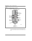
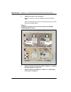
Figure 34
Right ear bracket installed on the chassis
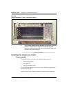
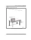
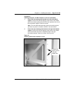
5 Place the chassis on the chassis guide brackets.
Carefully slide the chassis into the rack/cabinet until the ear brackets
come to rest against the rack/cabinet support.
Bracket flange marked
with an “R”. Attach this
ear bracket to the right-
hand side of the
chassis.
Attach the
ear bracket to
these holes.