


Page 188 of 332 Chapter 14 — Installing Power Failure Transfer Units
553-3021-209 Standard 3.00 April 2000
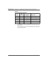
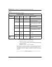
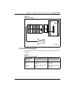
Table 35
Control and power connections on cable J1
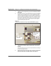
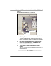
5 Connect the Attendant Console to the PFTU:
• Attendant Console 14 Tip (14T) to ground
• 3 Tip (3T) of PFTU to 11 Ring (11R) of Attendant Console (power
fail transfer switch)
• Attendant Console 11 Tip (11T) to ground
Note:
The AUX cable on the Option 11C Mini does not provide power
to the M2250 Attendant Console. Two Digital Line Card TNs or an
Attendant Console power supply provide power to the M2250 Attendant
Console.
—————————— End of Procedure ——————————
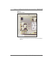
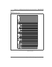
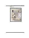
J1 Cable from QUA6 (see Figure 58 on page 189)
Function
Pair
Number
Pair
Color
Connects
to
Cross-connect to
Control
1T W-BL (ALM) Not used.
1R BL-W BRTN W-BL 1-dot connection on AUX
cable from the chassis
2T W-O PFTS W-O 1-dot connection on AUX
cable from the chassis. Transfer
begins by applying ground to this
lead.
2R O-W BRTN BL-W 1-dot connection on AUX
cable from the chassis
3T W-G (TC) Console transfer switch. See
console connections. Transfer
begins by applying ground to this
lead.
3R G-W Not used.
4T W-BR Not used.
4R BR-W Not used.
PFTU
power
25T
25R
S-V
V-S
-48 V
-48 V
O-W 1-dot connection on AUX
cable. Maximum 250 mA draw on
O-W lead.