


Chapter 2 — Identifying the Option 11C Mini equipment Page 41 of 332
Option 11C Mini Planning and Installation Guide
• additional Modem Eliminator (NULL Modem without hardware
handshaking). The A0601397 converter may be required to interface the
DTE to the system.
• industry-standard Ethernet Medium Access Unit (MAU)
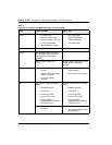
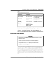
Differences between Option 11C Mini and Option 11C
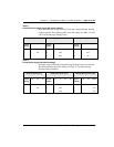
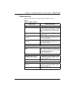
Refer to Table 7 for a comparison of the Option 11C Mini and Option 11C
systems.
Table 7
Comparison of Option 11C Mini and Option 11C
Item Option 11C Mini Option 11C
Physical packaging Main Chassis NTDK91
Chassis Expander NTDK92
Main cabinet NTAK11
Two copper cables connect the
Main Chassis to the Chassis
Expander.
Fiber-optic cable connects the
Main Cabinet to the Expansion
Cabinet (upgraded systems may
still have copper cable
connection).
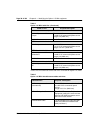
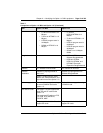
Capacity Main Chassis:
• 4 physical slots
• logical slots (slots 1-6)
Chassis Expander
• 4 physical slots
slots (slots 7-10)
Main Cabinet:
• 10 physical slots
(slots 1-10)
Expansion Cabinet
• Up to 4 additional NTAK11
cabinets can be connected
with fiber-optic cable
(slots 20-50)
Supports up to 144 lines Supports up to 700 lines
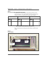
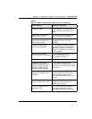
Chassis installation Four chassis installation options:
• vertically on a wall
• horizontally on a wall
• rack/cabinet
•table
Two chassis installation options:
•wall
• floor
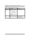
Cooling Forced air, thermally controlled
cooling
(Fan installed inside chassis)
convection cooling