


Page 32 of 332 Chapter 2 — Identifying the Option 11C Mini equipment
553-3021-209 Standard 3.00 April 2000
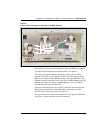
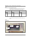
Power switch
There is a power switch on the front of the NTDK91 Main Chassis and the
NTDK92 Chassis Expander. Use this switch to turn the Option 11C Mini
power on and off. See Figure 5 on page 34.
Power status indicator
There is a power status indicator (LED) on the front cover (top left-hand
corner) of the Main Chassis and the Chassis Expander. When the LED is
green, the power is in operation. When the LED is off, there is a power failure
of one of the power outputs. See Figure 5 on page 34.
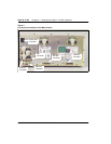
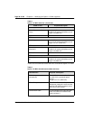
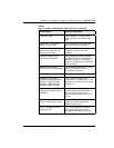
Power supply DIP switch settings
Use a DIP switch to set ringing voltages, ringing frequencies, and message
waiting voltages. See Table 2 and Figure 5 on page 34 for all DIP switch
setting options. Typical settings are shown for the following regions:
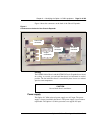
• “Asia Pacific/Cala power supply DIP switch settings” on page 33
• “Europe power supply DIP switch settings” on page 33
• “North American power supply DIP switch settings” on page 34
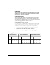
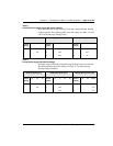
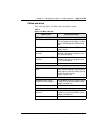
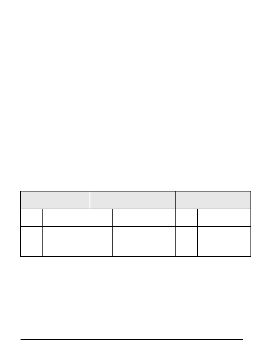
Table 1
Power supply DIP switch settings
Ringing Frequency (Hz) Ringing Amplitude (Vrms) Message Waiting Lamp (VDC)
Switch
Setting
20 25 50
Switch
Setting
70 75 80 86
Switch
Setting
-120 -150 Disable
1 ON OFF ON 3 OFF ON ON ON 6 NOT USED
2 ON ON OFF 4 OFF OFF ON ON 7 OFF OFF ON
5 OFF OFF OFF ON 8 OFF ON X