


Chapter 3 — System and site requirements Page 63 of 332
Option 11C Mini Planning and Installation Guide
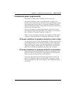
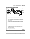
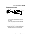
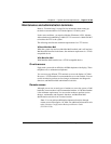
Figure 8
Typical hardwired Isolation Transformer wiring plan
••
•
•
• •
•
553-8323.EPS
Notes:
1
Power source is site dependent. It may be from a shared panel or transformer. Wiring may vary
accordingly. Wiring to panel must be housed in conduit.
2
Make SPG at the transformer secondary. If the transformer secondary has no isolated secondary
ground lug, make SPG by connecting all system ground lines to the chassis lug on the transformer
case. An insulated ground connection must be made between the SPG and a known building ground
reference, as per Note 3.
3
Terminate the Option 11 SPG insulated ground conductor as near as possible to the main building
ground reference. Isolate the ground bus from panel housing if permitted by local codes. Conductor
should be minimum AWG #6 (metric #40) at all points.
4
Transformer primary wires must be in conduit. Wiring to receptacles must be in conduit unless they are
mounted on the transformer case.
5
Connection can be made by metallic conduit. Additional copper conductor recommended.
6
Minimum AWG #6 (metric #40) insulated copper conductor connected to FGND lug on the Option 11
cabinet. Route separately from AC power cable.
7
Separate breaker required for each Option 11 Main cabinet. Breakers must be mounted on transformer
if the receptacles are. If they are in a panel served by the transformer secondary, all connections
between the receptacles and transformer must be in conduit. The Main Chassis and the Chassis
Expander can coexist on the same breaker.
8
Connect secondary neutral (X0) to system SPG.
Note 1
Note 3
Shared
Panel
Gnd Bus
Neutral Bus
Note 5
Note 4
Option 11
Cabinet
Gnd Lug
Note 8
Note 2
Note 7
Note 6
240V IG
Receptacle
120V IG
Receptacle
Isolation
Transformer
Note 4