


Chapter 17 — Connecting the telephones Page 239 of 332
Option 11C Mini Planning and Installation Guide
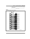
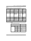
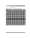
Table 49
Terminal Number assignments — Main Chassis and Chassis Expander
Physical slot Logical slot First TN...Last TN Cable Chassis
1 1 01 00...01 15 Card 1 Main
2 2 02 00...02 15 Card 2 Main
3 3 03 00...03 15 Card 3 Main
4 4
5
6
04 00...04 15
05 00...05 15
06 00...06 07
06 08...06 15
Card 4/Card 6
(see note)
Card 5/Card 6
(see note)
Card 4/Card 6
(see note)
Card 5/Card 6
(see note)
Main
Main
Main
Main
7 7 07 00...07 15 Card 7 Expander
8 8 08 00...08 15 Card 8 Expander
9 9 09 00...09 15 Card 9 Expander
10 10 10 00...10 15 Card 10 Expander
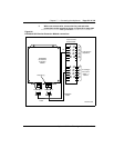
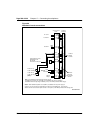
Note:
Refer to the labels on the back of the Main Chassis. See Figure 52 on page 179.
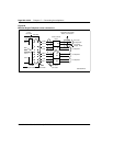
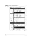
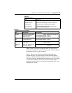
Table 50
Power Failure Transfer Unit connections
QUA6 J1 Cable
Function Pair Color Connects to
PFT 1
5T
5R
W-S
S-W
Connect to the telephone
6T
6R
R-BL
BL-R
Connect to the telephone
line card
7T
7R
R-O
O-R
Connect to the central
office trunk
8T
8R
R-G
G-R
Connect to the trunk line
card