


Chapter 4 — Creating an equipment layout plan and a card slot assignment plan Page 71 of 332
Option 11C Mini Planning and Installation Guide
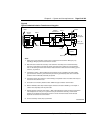
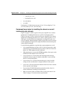
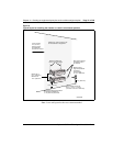
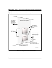
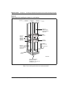
Figure 9
Typical layout for installing the chassis on a wall in a horizontal position
Note:
Leave wall space for the cross-connect terminal.
7
8
9
10
Power
Fan
N
E
T
W
O
R
K
S
7
8
9
10
Pow
er
Fan
N
E
T
W
O
R
K
S
Main
Chassis
Chassis
Expander
Maximum of
21 in. (533 mm)
Minimum of
12 in. (305 mm)
Draw 2 vertical lines
18.5 in. (470 mm)apart
Each chassis measures
8.4 in. x 17.2 in. x 12.8 in.
(213 mm x 437 mm x 325 mm)
Distance from
edge of backboard
to isolated
ground outlet
0 - 27 in. (686 mm)
Leave at least
2 in. (51 mm)
between edge
of backboard
and corner of room
Allow 24 in. (610 mm) at the top
for miscellaneous equipment
Draw horizontal line
for bottom hole of
ear bracket
10 in. (254 mm)
Recommended lowest position
for chassis installation is
10 in. (254 mm) from floor
12 in. (305 mm)
553-9034