


Chapter 12 — Installing the circuit cards Page 165 of 332
Option 11C Mini Planning and Installation Guide
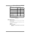
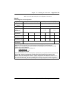
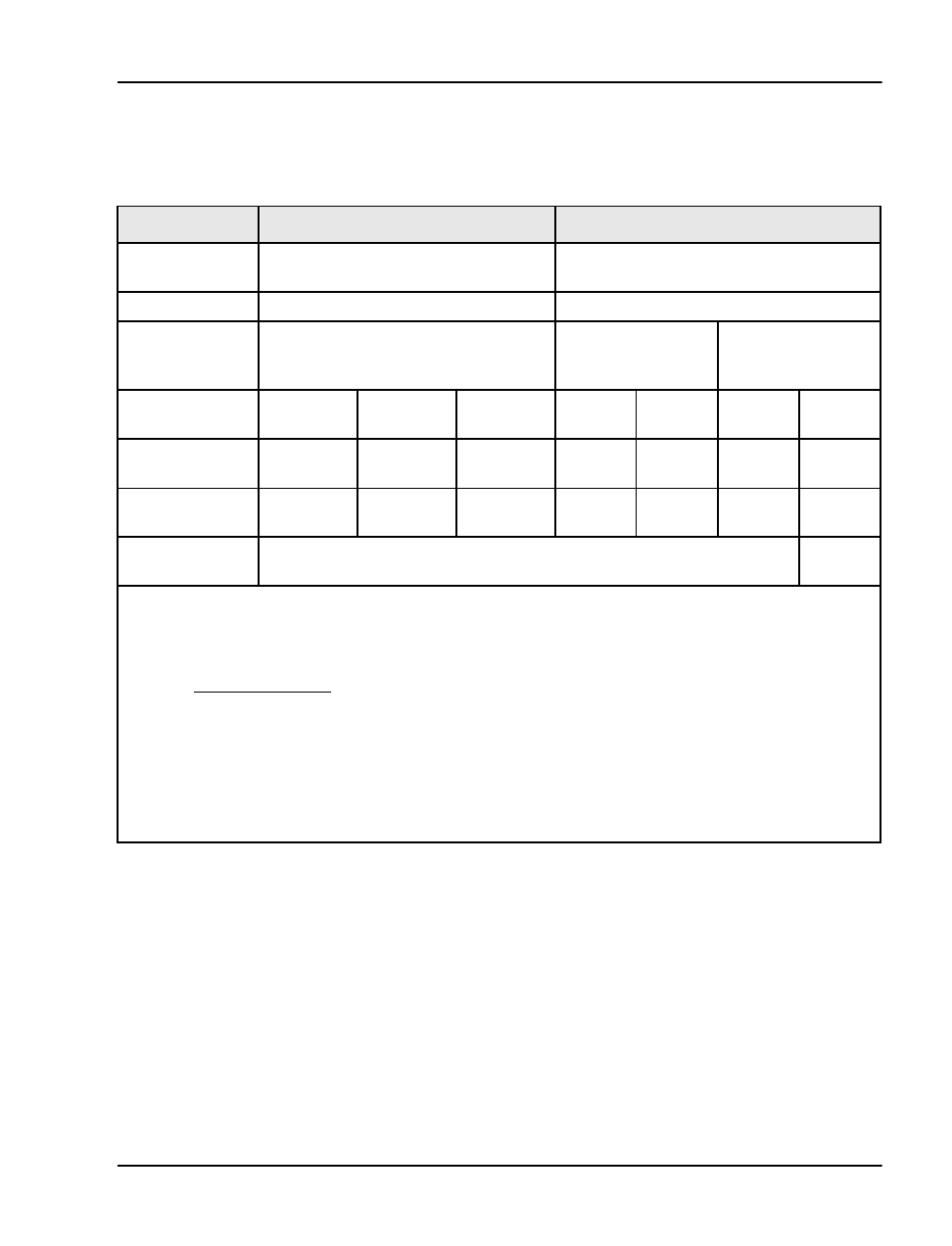
Table 33 provides OPS analog line card configuration information.
Table 33
OPS analog line card configuration
Application On-premise station (ONS) Off-premise station (OPS)
Class of service
(Note 1)
ONS OPS
Loop resistance 0 - 460 ohms 0 - 2300 ohms
Jumper strap
setting
(See Note 6)
Both JX. 0 and JX.1 off Both JX. 0 and JX.
1 off
Both JX. 0 and JX.
1 on
Loop loss dB
(See Note 3)
0-1.5 >1.5-2.5 2.5-3.0 0-1.5 1.5-2.5 2.5-3.0 4.5-15
TIMP
(See Notes 1, 4)
600¾ 600¾ 600¾ 600¾ 600¾ 600¾ 600¾
BIMP
(See Notes 1, 4)
600¾ 3COM1 3COM2 600¾ 3COM1 3COM2 3COM2
Gain treatment
(See Note 5)
No Ye s
Note 1:
Configured in the Single line Telephone Administration program (LD 10).
Note 2:
The maximum signaling range supported by the OPS analog line card is 2300 ohms.
Note 3:
Loss of untreated (no gain devices) metallic line facility. Upper loss limits correspond to loop
resistance ranges for 26 AWG wire.
Note 4:
Default software impedance settings are:
ONS CLS
OPS CLS
TIMP: 600 ohms 600 ohms
BIMP: 600 ohms 3COM2
Note 5:
Gain treatment, such as a voice frequency repeater (VFR), is required to limit the actual OPS loop
loss to 4.5 dB, maximum. VFR treatment of metallic loops having untreated loss greater than 15dB
(equivalent to a maximum signaling range of 2300 ohms on 26 AWG wire) is not recommended.
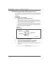
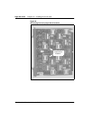
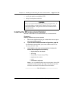
Note 6:
Jumper strap settings JX> 0 and JX. 1 apply to all eight units; “X” indicates the unit number, 0-7.
“OFF” indicates that a jumper strap is not installed across both pins on a jumper block. Store straps that are
not in use on the OPS analog line card by installing them on a single jumper pin as shown in Figure 46.