


(Revised 2010-7-2) page 14 of 145
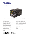
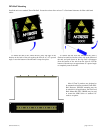
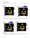
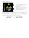
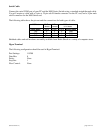
FRONT PANEL
From Top to Bottom:
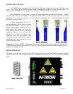
Gigabit Ports 1000 Base-SX Connections
Fiber Ports 100 Base-FX Connections
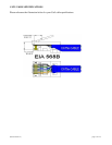
RJ45 Ports Auto sensing 10/100 Base-TX Connections
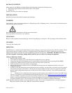
Green LED lights when Power is supplied to the module
NOTE: The RJ45 data port has two LED‟s located at the side of the connector. The bottom LED indicates
LINK status, and the top LED indicates ACTIVITY.
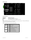
LED’s: The table below describes the operating modes:
LED
Color
Description
GREEN
Power is Applied
OFF
Power is OFF
LNK
GREEN
10/100/1000Mb Link between ports
OFF
No Link between ports
ACT
GREEN
Data is active between ports
OFF
Data is inactive between ports