


(Revised 2010-7-2) page 18 of 145
CONNECTING THE UNIT
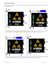
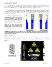
For FX/FXE units, remove the dust cap from the fiber optic connectors and connect the fiber optic
cables. The TX port on the FX/FXE models should be connected to the RX port of the far end station. The
RX port on the FX/FXE versions should be connected to the TX port of the far end station.
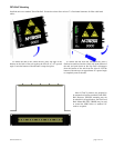
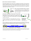
For 10/100 Base-TX ports, plug a Category 5E twisted pair cable into the RJ45 connector. Connect
the other end to the far end station. Verify that the LNK LED‟s are ON once the connection has been
completed. To connect any other port to another Switch or Repeater, use a standard Category 5 straight
through or crossover cable.
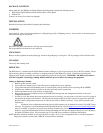
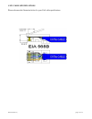
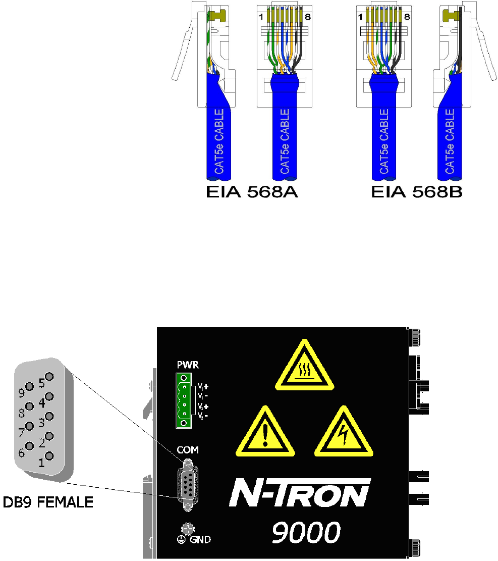
N-Tron recommends the use of
pre-manufactured Cat5E cables to ensure
the best performance. If this is not an
option and users must terminate their own
ends on the Cat5E cables; one of the two
color coded standards shown to the right
should be utilized. If a user does not
follow one of these two color code
standards then the performance and
maximum cable distance will be reduced
significantly, and may prevent the switch
from establishing a link.
Warning: In absence of RSTP or Proprietary Ring control on the specific ports connected, creating a port
to port connection on the same switch (i.e. loop) is an illegal operation and will created a broadcast storm
which will crash the network!
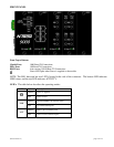
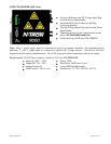
SERIAL INTERFACE
The 9000 series switches provide an EIA-232 interface accessed via a 9 pin female connector (labeled
„COM‟ on the unit). This is used to access the Command Line Interpreter (CLI). The pin-outs are shown
below: