207
Routing Tables Section 8-4
8-4 Routing Tables
When the FINS communications service is used, routing tables must be cre-
ated in advance. Routing tables are required in the following circumstances.
• When communicating with a PLC or computer on another network (e.g.,
remote programming or monitoring using FINS messages or a CX-Pro-
grammer)
• When multiple Communications Units are mounted to a single PLC (i.e.,
CPU Unit).
• When routing tables are used for one or more other nodes on the same
network.
It is not necessary to set routing tables if one Communications Unit is
mounted to the PLC and the nodes are connected as one network. The rout-
ing tables are required not only for nodes communicating via the FINS com-
munications service but also for all relay nodes on the network.
8-4-1 Routing Table Overview
The routing tables describe the transmission path for FINS messages when
the FINS communications are used. It consists of two tables: A local network
table and a relay network table.
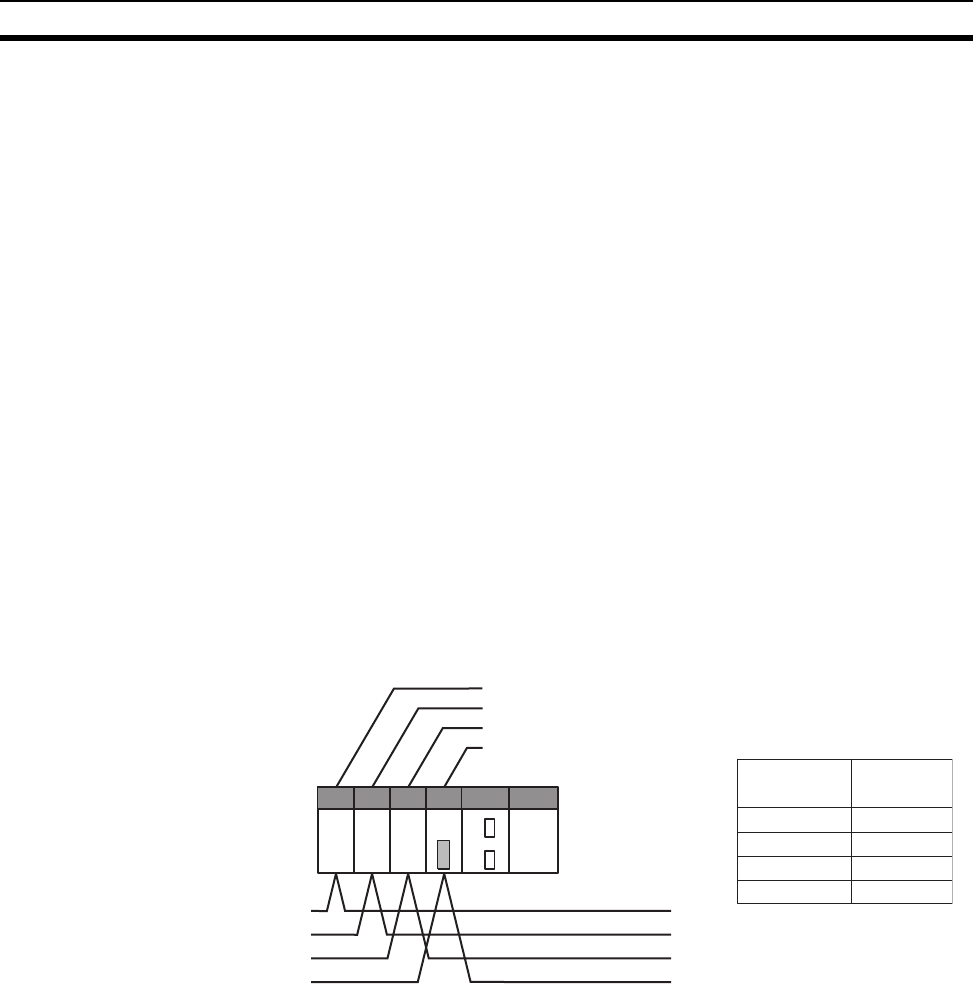
Local Network Table The local network table is a table describing the correspondences among unit
numbers of the Communications Units and Boards mounted to each node.
Note 1. The unit number is set (0 to F: 1 to 15) using the rotary switch on the front
of the EtherNet/IP Unit (built-in port).
2. The network address is the number of the network (1 to 127) to which the
Communications Unit or Board is connected. It is set when the local net-
work table is created.
Relay Network Table A relay table is a table that shows the nodes to which data should be sent first
in order to send data to a network that is not connected to the local node. It
shows the correspondence between the address of the final destination net-
work, and the network address and node address of the first relay point of the
path to reach there. When internetwork communications are carried out, the
end network can be reached by following the relay points.
Example
Unit #04
Unit #05
Unit #06
Unit #07
Network #1
Network #2
Network #3
Network #4
Local Network Table
Local network
address
Unit number
1
2
3
4
04
05
06
07


