294
Message Service Transmission Delay Section 10-5
10-5 Message Service Transmission Delay
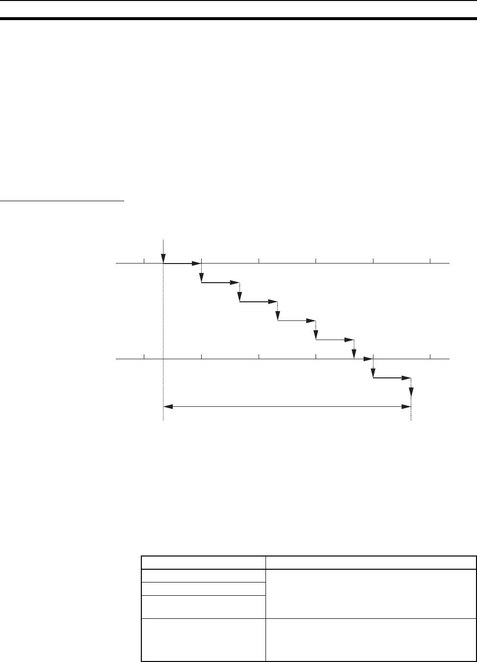
This section explains the maximum transmission delay that can occur
between the execution of a SEND(090), RECV(098), or CMND(490) instruc-
tion in the ladder program until completion of the instruction. This delay does
not include the time required for the tag data link or the execution time of the
ladder program itself.
10-5-1 Maximum Transmission Delays (Excluding Delays in the Network)
Use the following equation to calculate the maximum transmission delay that
can occur between the execution of a SEND(090) or RECV(098) instruction in
the ladder program until completion of the instruction.
SEND(090) Instruction
Maximum transmission delay =
CPU Bus Unit service cycle (local node)
+ CPU Bus Unit service processing time (local node)
+ Send processing
+ Transmission delay
+ Receive processing
+ CPU Bus Unit service cycle (remote node)
+ CPU Bus Unit service processing time (remote node)
CPU Bus Unit Service
Cycle (Local Node)
The following table shows the service cycle, which depends on the CPU Unit’s
CPU processing mode setting.
Note CJ2 CPU Units support only Normal Mode.
Execution of SEND(090)
in user program
CPU Bus Unit service cycle
(Local node)
CPU Bus Unit service processing time
(Local node)
Send processing
Transmission delay
Receive processing
CPU Bus Unit service cycle
(Remote node)
CPU Bus Unit service
processing time (Remote node)
CPU data set
processing
Maximum transmission delay
CPU execution mode Processing time details
Normal Mode (See note.) One CPU Unit cycle time
Priority peripheral servicing
Parallel processing with syn-
chronous memory access
Parallel processing with asyn-
chronous memory access
0.2 ms + peripheral servicing time (1 ms max. for
peripheral servicing of each Special I/O Unit, CPU
Bus Unit, peripheral port, RS-232C port, and Inner
Board)


