292
Tag Data Link Performance for CJ2M Built-in EtherNet/IP Ports Section 10-4
If the same RPI is set for all connections, 12 ms is the lowest setting that can
be used.
■ Calculation Example
(1,000 ÷ 12 [ms] (RPI) + 1,000 ÷ 100 [ms] (heartbeat transmission period)) ×
32 (connections) = 2,987 pps < 3,000 pps
10-4-2 Tag Data Link I/O Response Time
With tag data links, if the data in the data link area for a node changes due to
an input to that node, a certain amount of time is required for the data in data
link area at another node to be updated and output.
The I/O response time for tag data links can be calculated for a CJ2M built-in
port in the same was as it can for a CJ2H built-in port (refer to 10-2-4 Chang-
ing the RPI). Here, formulas to calculate guideline I/O response times are pro-
vided. (Tag data link delays are ignored because the data link size handled by
the built-in CJ2M port is small.)
Maximum I/O Response Time
Input ON delay + Cycle time of sending PLC × 2 + RPI + Cycle time of receiv-
ing PLC × 2 + Output ON delay
Minimum I/O Response Time
Input ON delay + Cycle time of sending PLC + Cycle time of receiving PLC +
Output ON delay
*All nodes use CJ2M built-in ports.
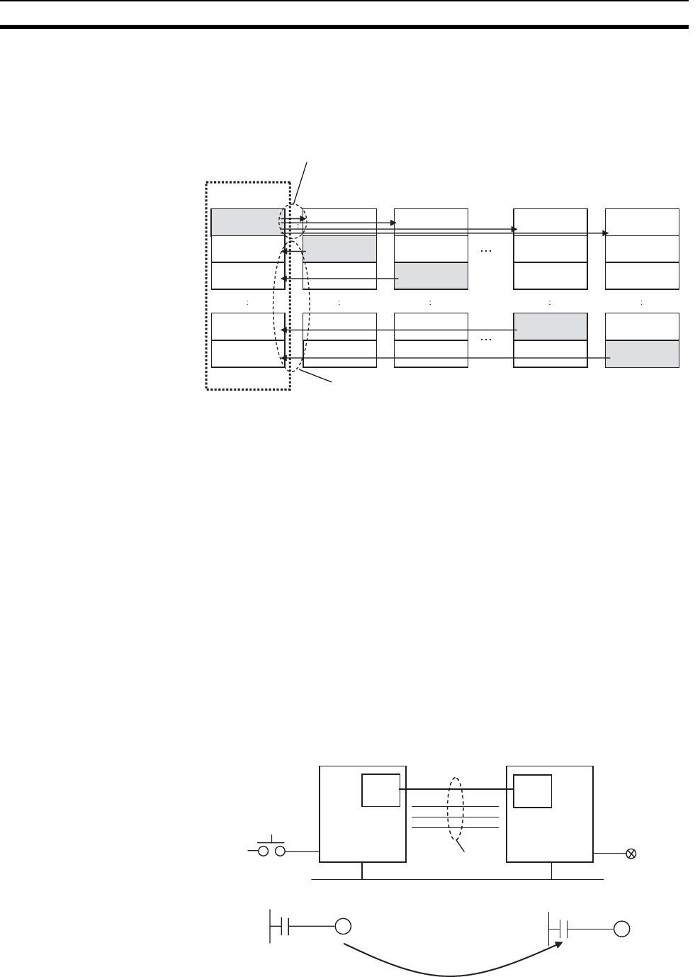
Node 1
Send 20 words
Receive 20 words
Receive 20 words
Send connections = 16
(20 words × 16 = 320 words)
Node 2
Send 20 words
Send 20 words
Send 20 words
Send 20 words
Receive 20 words
Receive 20 words
Receive 20 words
Receive 20 words
Receive 20 words
Receive 20 words
Receive 20 words
Receive 20 words
Receive 20 words
Receive 20 words
Receive 20 words
Receive 20 words
Receive 20 words
Receive 20 words
Receive 20 words
Receive 20 words
Receive 20 words
Receive 20 words
Node 3
Node 16
Node 17
Receive connections = 16
(20 words × 16 = 320 words)
All connections
Cycle time: 5 ms
Input ON response time:
1.5 ms
Input
Output
Data link
EtherNet/IP
Connection
RPI: 12 ms
PLC #1
Node 1
PLC #2
Node 2
20
words
20
words
Cycle time: 10 ms
Output ON response
time: 2.0 ms


