37
Switch Settings Section 3-2
3-2-2 CJ-series EtherNet/IP Units and CJ2 Built-in EtherNet/IP Port
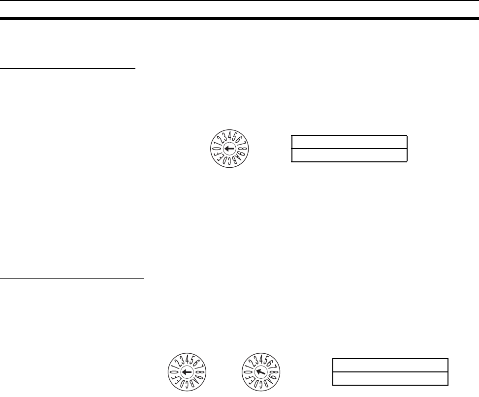
Setting the Unit Number
The unit number is used to identify individual CPU Bus Units when more than
one CPU Bus Unit is mounted to the same PLC. Use a small screwdriver to
make the setting, taking care not to damage the rotary switch. The unit num-
ber is factory-set to 0.
Note (1) Turn OFF the power supply before setting the unit number.
(2) If the unit number is being set for the first time or changed, then I/O tables
must be created for the PLC.
(3) With CS-series and CJ-series PLCs, dedicated areas are automatically
allocated in the CIO Area and DM Area according to the unit numbers that
are set. For details, refer to SECTION 4 Memory Allocations.
Setting the Node Address
With the FINS communications service, when there are multiple EtherNet/IP
Units connected to the Ethernet network, the EtherNet/IP Units are identified
by node addresses. Use the node address switches to set the node address
between 01 and FE hexadecimal (1 to 254 decimal). Do not set a number that
has already been set for another node on the same network.
The left switch sets the sixteens digit (most significant digit) and the right
switch sets the ones digit (least significant digit). The node address is factory-
set to 01.
Note Turn OFF the power supply before setting the node address.
Relationship to IP
Addresses
When IP addresses are generated automatically (either dynamic or passive),
the rightmost byte of the host ID of the IP address of the EtherNet/IP Unit or
built-in EtherNet/IP port is set to the same value as the node address. (Refer
to Section 5 Determining IP Addresses.) If the same node address value can-
not be used, the IP address table method or the combined method must be
used for address conversion. (For details, refer to SECTION 5 Determining IP
Addresses.)
If the FINS communications service is not being used on the Ethernet net-
work, then it is all right for the same node address to be set on two or more
EtherNet/IP Units or built-in EtherNet/IP ports. The setting, however, must be
made within a range of 01 to FE. If a value outside of this range is set, the MS
indicator will light red, the 7-segment display will indicate code H4 (node
address setting error), and the EtherNet/IP Unit or built-in EtherNet/IP port will
stop operating.
UNIT
No.
Setting range:
0 to F
NODE
No.
× 16
0
× 16
1
Setting range:
01 to FE (1 to 254 decimal)


