265
Communications System Section 10-1
10-1-3 Network Transmission Delay Time
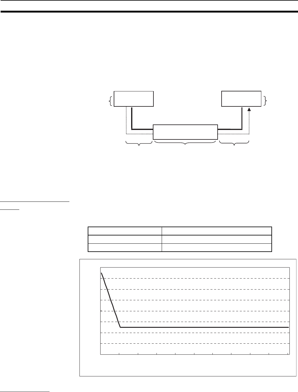
In an EtherNet/IP network, the tag data link packets are sent once each
packet interval (RPI), but several delays occur between the transmission of
packets from each node and the arrival of the packets at the destination
nodes. The following diagram shows the 4 major delay sources.
Total network transmission delay = (1) Send processing delay + (2) Ca-
ble delays + (3) Switching hub delay
+ (4) Receive processing delay
The lengths of these delays depend on many factors, such as the tag data link
connection settings (number of connections and data sizes), number of
nodes, the switching hub being used, and cable lengths. Each delay is
described in detail below.
1. Send Processing
Delay
The send processing delay is the delay that occurs within the EtherNet/IP Unit
or built-in EtherNet/IP port when data packets are sent once each packet
interval. This delay varies with the RPI error shown in the following graph, so
the send processing time is the maximum value for each RPI.
2. Cable Delay The cable delay is the time required for the data signal to pass through the
cable and reach the destination. When an STP (shielded twisted-pair) cable of
category 5, 5e, or higher is being used, the maximum cable delay is 545 ns/
100 m. The cable delay represents a very small percentage of the total tag
data link delay.
EtherNet/IP
Unit
Switching hub
(1) Send
processing
delay
(
2
)
Cable dela
y(
2
)
Cable dela
y(
3
)
Switchin
g
hub dela
y
EtherNet/IP
Unit
(4) Receive
processing
delay
Data
Packet interval (RPI) RPI error (±) (%)
0.5 to 1,000 ms 15 − (RPI (ms) ÷ 100)
1,000 ms to 10,000 ms 5% of the RPI
0
2
4
6
8
10
12
14
16
0 1,000 2,000 3,000 4,000 5,000 6,000 7,000 8,000 9,000 10,000
RPI [ms]
RPI error (±)[%]


