


1-33170-A2-GB20-20 December 1996
Physical Description
The
E1 DSU/CSU series of products consists of a
Model 3172 DSU/CSU (2-port) and a Model 3174
DSU/CSU (4-port).
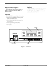
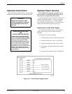
Front Panel
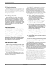
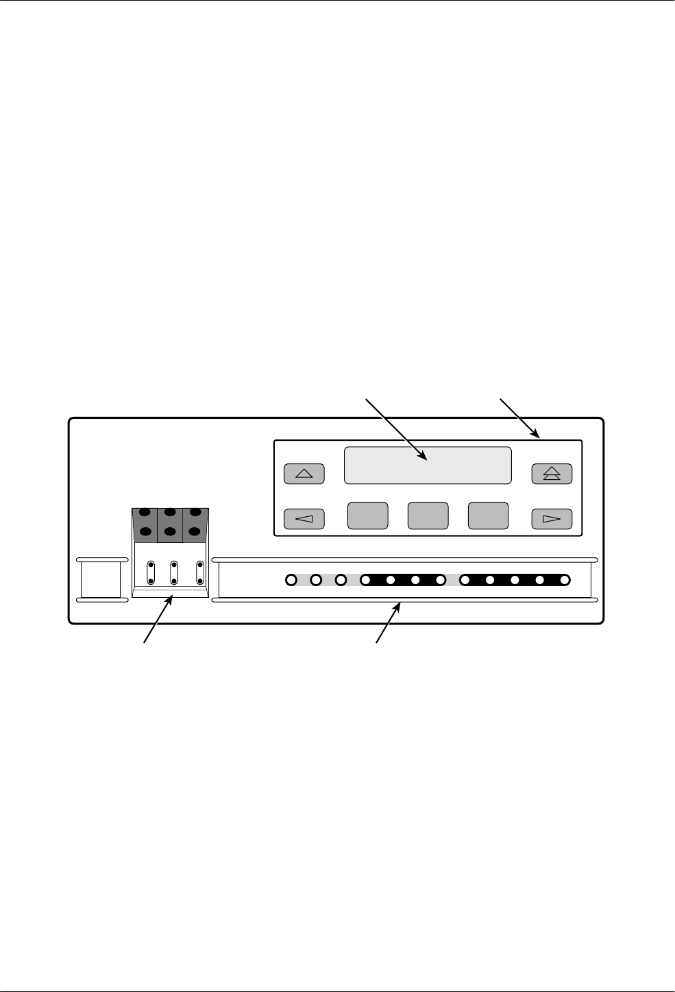
The E1 DSU/CSU front panel (Figure 1-1) contains,
• One 2-line, 16-alphanumeric-character-per-line
liquid crystal display (LCD)
• One 7-button keypad (three Function and four
directional keys)
• Twelve light-emitting diodes (LEDs)
•
Six test jacks
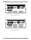
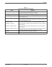
Rear Panel
The E1 DSU/CSU rear panel contains the connectors
and switches required for the operation of the E1
DSU/CSU (Figures 1-2 and 1-3). The connectors and
switches are described in T
able 1-1.
F1 F2 F3
OK
FAIL TEST SIG OOF ALRM
NETWORK RXD
EER SIG ALRM PDVOOF BPV
LCD
ACCULINK
In
Out
In
Out
In
Out
NET
NET
MON
EQPT
MON
DTR TXD CTS RTS
496-14539-0
3
KEYPAD
TEST JACKS LEDs
Figure 1-1. Front Panel