Operation
3-113170-A2-GB20-20 December 1996
Selecting the DTE Drop/Insert
or Data Port for LED Display
Use the LED command on the Control branch to select
which port’s (DTE Drop/Insert or data port) status appears
on the five shared LEDs on the front panel.
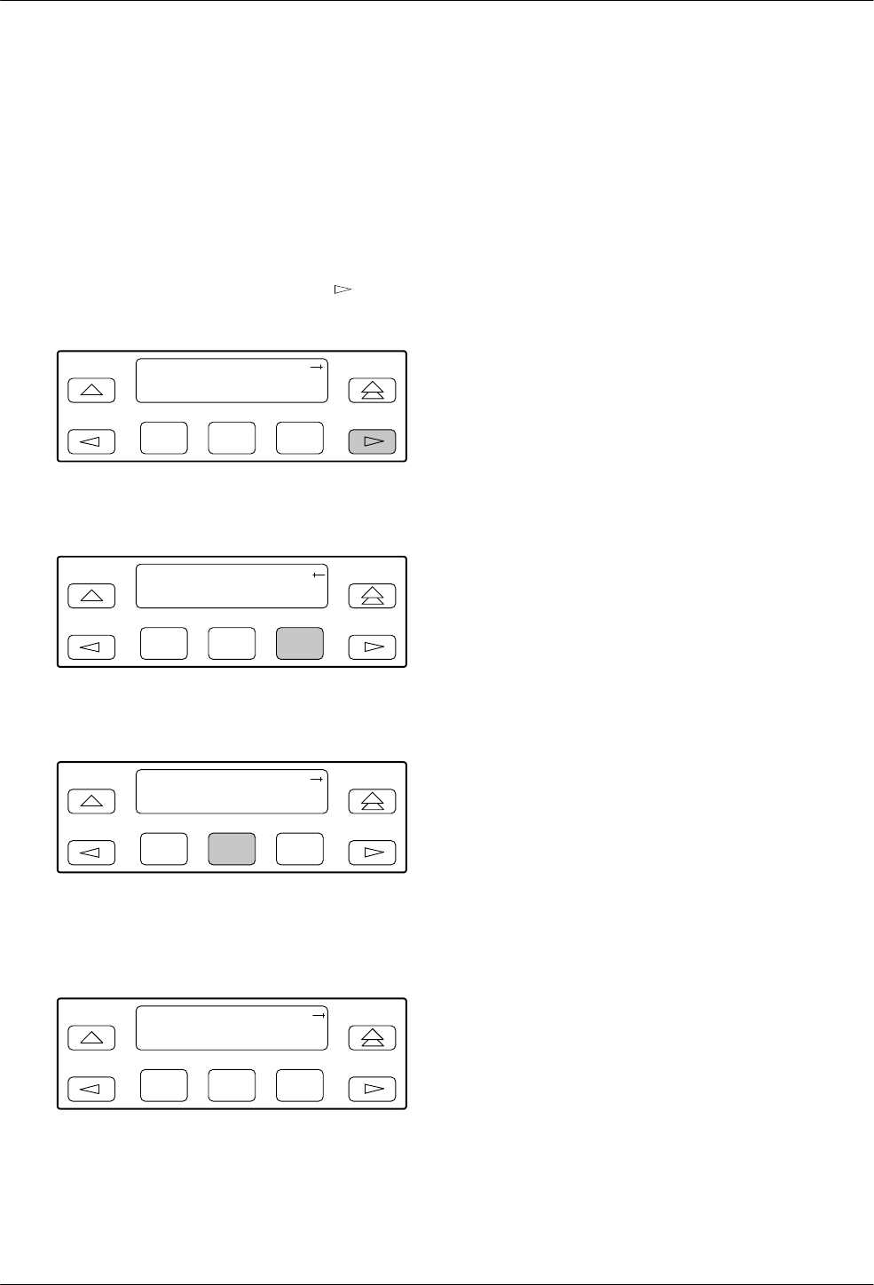
To select a port for LED display,
1. From the top-level menu screen, press
once to
scroll the Ctrl name onto the screen.
F1
DS
U E
1 CEPT
Stat Test Cnfig
F2
F3
2. Press
F3 to select Ctrl.
F1
DS
U E
1 CEPT
Test Cnfig Ctrl
F2
F3
3. From the Control screen, select LED.
F1
Control:
Rel LED ClrReg
F2
F3
The currently selected port name appears on the
top line of the LCD. DTE indicates the DTE
Drop/Insert port.
F1
LED Dsply: DTE
DTE Prt1 Prt2
F2
F3
4. From the LED Dsply screen, press the Function
key that corresponds to the DTE Drop/Insert or
data port for which you want the LEDs to display.
Use the scroll keys, if necessary
.
Select DTE to monitor the DTE Drop/Insert port’s
SIG, OOF
, ALRM, PDV
, and BPV status signals
on the shared LEDs.
Select a particular data port to monitor the data
port’
s DTR, TXD, RXD, CTS, and R
TS control
signals on the shared LEDs.
Changing Configuration
Options
The
E1 DSU/CSU is an intelligent device that displays
only valid options for the current configuration.
Therefore, you are only presented with menu choices that
are consistent with the current configuration and
operational state of the E1 DSU/CSU; invalid
combinations of configuration options do not appear. For
example, menus displayed for the Model 3172 (2 ports)
and the Model 3174 (4 ports) differ due to the number of
ports available. Also, if the DTE Drop/Insert interface
selection is disabled, many of the menu choices do not
appear
. Be aware that although all options are shown in
this guide, what you see on your E1 DSU/CSU varies with
your configuration.
The E1 DSU/CSU offers four sets of configuration
options located in the following memory areas:
• Active (Activ). The configuration option set active
for the E1 DSU/CSU is stored here. Before a
configuration option set becomes active for the E1
DSU/CSU, you must save the set to the Active area.
When the E1 DSU/CSU is shipped from the
factory, the Active configuration option set is
identical to the Factory set. This area can be written
to and controls the current operation of the device.
• Customer 1 (Cust1). The first of two sets of
customer-defined configuration options. This area
can be written to.
• Customer 2 (Cust2)
. The second of two sets of
customer-defined configuration options. This area
can be written to.
• Factory (Fact). This is a set of configuration
options preset at the company
. This set is
determined by what is considered to be the most
common configuration used in the E1 DSU/CSU
market. Factory options are read-only.


