


ACCULINK 317x E1 DSU/CSU
C-10 December 1996 3170-A2-GB20-20
Table C-5
(2 of 3)
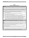
Data Port Channel Configuration Options
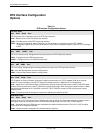
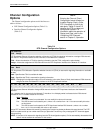
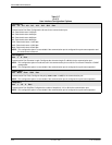
Port Rate: 384
Next 64 128 192 256 320 384 448 512 576 640 704 768 832 896 960 1024 1088
1
152 1216 1280 1344 1408 1472 1536 1600 1664 1728 1792 1856 1920 1984 Prev
OR
Next 56 1
12 168 224 280 336 392 448 504 560 616 672 728 784 840 896 952
1008 1064 1120 1
176 1232 1288 1344 1400 1456 1512 1568 1624 1680 1736 Prev
Data Port Rate (appears when using the block channel allocation method, or when a synchronous data port is assigned
to another synchronous data port). Designates the data rate for the port. Available selections depend on the current base
rate configured for the port. The factory default for Nx64 is 384 kbps, and for Nx56 is 336 kbps.
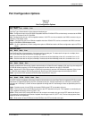
NOTE: This configuration option does not appear if the individual channel allocation method (Chan) is selected using the
Assign By configuration option.
NOTE: If time-slot 16 is reserved for signaling, the highest port rate (1984 or 1736) does not appear.
NOTE: Changing this configuration option from one rate to another deallocates all DS0 channels assigned to either the
Network E1 interface or the DTE Drop/Insert interface.
NOTE: When you enable EDL, 8 kbps of the total bandwidth allocated for this port is not available to the synchronous
data port. For example, if you select 256 kbps and EDL is enabled, only 248 kbps are available.
NOTE: When you enable EDL for a synchronous data port and the clock source (either primary or secondary) is set to
that synchronous data port, the external device must provide a clock of 8 kbps less than the expected data port
rate. For example, if you select 64 kbps, the external clock source must supply a 56 kbps clock signal.
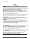
NOTE: For the 3174 DSU/CSU there is a hardware limitation that limits the combined bandwidth used by Port1 and
Port3 to a total of 2048 kbps and the combined bandwidth used by Port2 and Port4 to 2048 kbps. Thus, when
entering this menu, the rate choices are limited due to this constraint. This limitation only occurs in configurations
mapping a port to a port or when mapping ports to the DTE Drop/Insert interface and to the network.
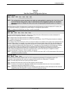
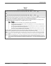
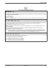
Start At:
Next Clear N1 N2 N3 N4 N5 N6 N7 N8 N9 N10 N11 ... N31 Prev
OR
Start At:
Next Clear D1 D2 D3 D4 D5 D6 D7 D8 D9 D10 D11 ... D31 Prev
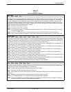
Data Port Channel Allocation (appears for the block method only). Designates the starting DS0 channel (N1–N31 for the
Network E1 interface and D1–D31 for the DTE Drop/Insert interface).
Available selections are only those DS0 channels that provide enough bandwidth (based on the configured data rate) to
be used as a starting channel number.
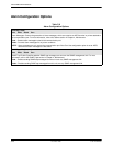
Select the desired starting channel number by pressing the Function key under that number. When you make the
selection, the E1 DSU/CSU allocates the correct amount of DS0 channels to support the data rate currently configured for
the port.
Clear – Deallocates all DS0 channels for this port from either the Network E1 interface or the DTE Drop/Insert interface.
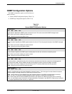
NOTE: This configuration option does not appear if the individual channel allocation method (Chan) is selected using the
Assign By configuration option, or if Prt
n
is selected using the Assign T
o configuration option.