


Introduction
1-53170-A2-GB20-20 December 1996
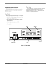
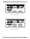
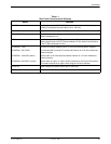
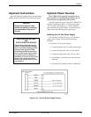
Table 1-1
Rear Panel Connectors and Switches
Name
Function
POWER Supplies power to the E1 DSU/CSU by providing an attachment for the ac power
module or the optional dc power cable (+24 or –48 Vdc).
AUX PORT Supports SNMP LAN Adapter or daisy-chain connections.
COM PORT Provides access to a locally connected PC, an ASCII terminal or printer, or an
SNMP management link.
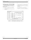
DTE Provides access to the DTE Drop/Insert interface. This interface is compatible
with the signal format of CCITT Recommendation G.703 and the frame structure
of CCITT Recommendation G.704.
NETWORK—120Ω
Provides an unkeyed modular jack for a 120 ohm balanced network interface.
NETWORK—75Ω TX/RX
Provides two BNC connectors (Transmit and Receive) for a 75 ohm unbalanced
network interface.
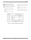
NETWORK—120Ω/75Ω (switch)
Selects either a 120 ohm balanced network interface or a 75 ohm unbalanced
network interface.
NETWORK—RX SHIELD (switch) Selects either an “open” or “earth” shield connection for the 75 ohm RX interface.
(This switch must be set to “open” when using the 120 ohm interface.)
CLOCK IN Used to attach an external clock to the E1 DSU/CSU.
PORTs 1– 4 Used to connect the customer’s synchronous data DTE to the E1 DSU/CSU.