


ACCULINK 317x E1 DSU/CSU
3-4 December 1996 3170-A2-GB20-20
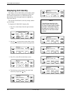
The scroll keys (
and
) serve one of two functions,
depending on whether a menu screen or a data entry
screen appears on the front panel.
For data entry screens, the
key scrolls one
character to the left while the
key scrolls one
character to the right.
For menu screens, the key scrolls to the previous
menu choice while the
key scrolls to the next menu
choice.
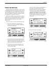
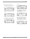
If a choice is available to the left of the screen, the
character ← appears on the top line. If a choice is
available to the right of the screen, the → character
appears on the top line. If choices are available to both the
right and the left of the screen, two arrows appear (
).
The arrows indicate that you must use the scroll keys to
bring the additional options onto the screen.
F1 F2
F3
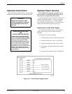
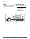
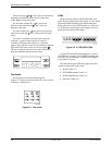
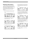
Test Jacks
Six test jacks are located on the front panel
(Figure 3-4). These are described in the T
est Jacks
section
in Chapter 4, Maintenance.
Figure 3-4. Test Jacks
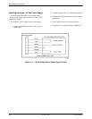
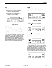
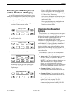
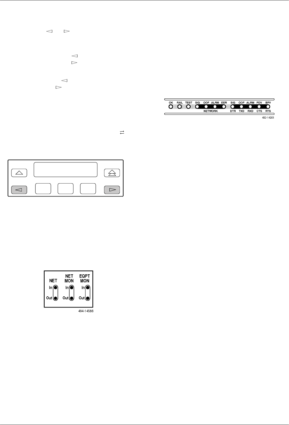
LEDs
There are twelve LEDs on the E1 DSU/CSU front
panel. The five LEDs on the right (Figure 3-5) are shared
between the DTE Drop/Insert port and the data ports.
Refer to the Selecting the DTE Dr
op/Insert or Data Port
for LED Display
section later in this chapter to choose
which port’
s status the LEDs display
.
Figure 3-5. E1
DSU/CSU LEDs
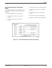
A green LED indicates normal operation. A yellow
LED indicates a warning (for the DTE Drop/Insert port)
or activity (for the data ports). Conditions are sampled
every tenth of a second.
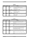
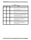
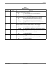
The twelve front panel LEDs are grouped into four
sections to indicate the status of the:
• System (Table 3-1)
• NETWORK interface (Table 3-2)
• DTE Drop/Insert Port (Table 3-3)
• Data Ports (Table 3-4)